# Bambu Labs X1 Carbon

When I first started on my 3D printing journey I was totally happy in trolling through Bambu Lab's Wiki pages, community forums and random websites and Youtube tutorials. However, my partner at the time found it overwhelming to try and locate the information, so I started off writing this document for her.

Unfortunately, she is no longer in the picture, deciding that there the community may be able to obtain use from it I have finalised the intial release of it and offer it for you to use for free.

If you find errors or omissions in it, or something that needs updating, then please sign up for an account, and you will be able to assist the community by correcting them.

# Acknowlegments

##### Bambu Studio

I would like to acknowledge that portions of this document were based off the WIKI pages of [Bambu Labs](https://wiki.bambulab.com).

# Introduction to CoreXY

CoreXY provides a fundamental building block of many computerized fabrication tools - cartesian motion - in a simple and adaptable format.

<span class="philSpan">**CoreXY is a technique, not an implementation**.</span> We sketch the concept and give a few examples as a platform that enables you to build new tools that are as unique as your ideas.

<span class="philSpan">**Fast**.</span> We believe in speed. CoreXY's (mostly) parallel kinematics mean that the motors, typically the largest source of inertia on a DIY-grade stage, are stationary. This permits rapid accelerations.

<span class="philSpan">**Simple**.</span> CoreXY can be implemented with only three structural plates, all of which can nest during fabrication.

<span class="philSpan">**Flexible**.</span> Whether your medium is fabric or aluminum, the principle behind CoreXY permits motion stages to be rendered in a variety of materials and a wide range of sizes.

## Kinematics

CoreXy is a design where two moters are utilised for the X and Y movements, where both belts are terminated onto the toolhead. Both motors are used to move the Toolhead in the X and Y directions. If only one motor is used then the toolheat will move in a diagonal direction.

As both motors are directly mounted to the chassis, and a single motor is not required to move the mass of the toolhead, it allows the motion speed of the toolhead to be moved much faster than the standard Cartesian implementation.

**Pros**

- **Higher Print Speeds**: The stationary X and Y motors reduce mechanical weight and momentum giving the motion system a mechanical advantage compared to other motor placement configurations.
- **Quality**: With the reduced weight and momentum the setup also results in reduced vibrations and increased repeatability at higher speeds.
- **Mechanicaly** **Optimized**: With the x and y motors out of the way the machine size compared to actual build volume ratio gives you more printing space with a smaller footprint. Unlike the hbot the corexy carriage isn’t problematic to twisting or buckling when x and y motors rotate in the same direction.

**Cons**

- **Maintenance**: The longer x and y belts introduce belt tensioning issues(belt stretch). The increased number of belt idlers increase maintance.
- **Scalabilty**: The belt stretch and tensioning issues introduces a design constraint as the machine size increases.

### CoreXY Motor Movement

<figure class="wp-block-table" id="bkmrk-motor-movement-direc"><table><thead><tr><th>Motor Movement</th><th>Direction</th></tr></thead><tbody><tr><td>Both Motors Move Clockwise</td><td>Carriage Moves Left</td></tr><tr><td>Both Motors Move Counter Clockwise</td><td>Carriage Moves Right</td></tr><tr><td>Both Motors Move Opposite of Each Other</td><td>Carriage Moves Toward &amp; Away</td></tr><tr><td>One Motor Moves</td><td>Carriage Moves Diagonal</td></tr></tbody></table>

</figure><div id="bkmrk-"></div><div id="bkmrk--1"></div>### Principle of Operation

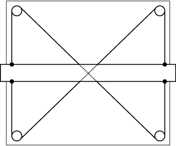
<table id="bkmrk-this-is-a-standard-d"><tbody><tr><td><div class="principle">![](https://corexy.com/principles1.png)</div>This is a standard drafting table. The horizontal bar is a straight-edge which can be moved up and down by the user. The criss-cross pattern of the cables stabilizes the bar and keeps it horizontal.

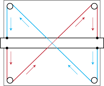
</td><td><div class="principle">![](https://corexy.com/principles2.png)</div>This effect can be seen by following the direction of motion of the two cables which comprise the mechanism. Note that all of the vertical arrows point in the same direction.

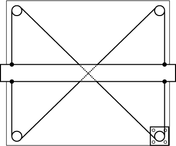
</td></tr><tr><td><div class="principle">![](https://corexy.com/principles3.png)</div>You could imagine attaching a stepper motor to one of the pulleys. Now, the horizontal bar can be moved up and down under computer control. This might be called a <span class="spanItalic">single-axis CNC stage.</span>

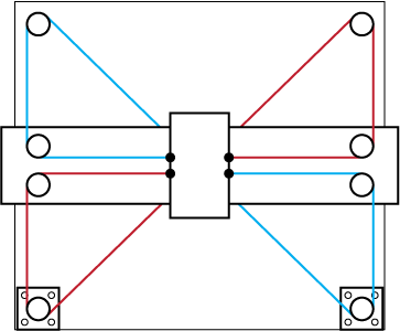
</td><td><div class="principle">![](https://corexy.com/principles4.png)</div>How might we modify this mechanism to convert it into a two-axis CNC stage? The illustrated mechanism above is one solution. Rotating both motors in the same direction results in horizontal motion. Rotating both motors in opposite directions results in vertical motion.

</td></tr></tbody></table>

# Reference Mechanism

![](https://corexy.com/reference.png)

##### References

- [Core\[X,Y\]](https://corexy.com)

# Introduction to Fused Deposition Modeling (FDM)

[![image.png](https://docs.home.schwetz.au/uploads/images/gallery/2025-05/scaled-1680-/1N9KP693EpN1QHAG-image.png)](https://docs.home.schwetz.au/uploads/images/gallery/2025-05/1N9KP693EpN1QHAG-image.png)

## The Process

Fused Deposition Modeling (FDM) is an additive manufacturing process where an object is formed by extruding melted material in a pre-determined path layer by layer. The process is as follows:

1. A computer program “slices” a 3D object into hundreds of thin cross sections.
2. The 3D printer accepts the sliced 3D model and begins heating a metal nozzle.
3. A long strand of thermoplastic is fed into the hot nozzle by a system of gears.
4. The nozzle is displaced horizontally by two belts to deposit the melted filament onto a build platform in a pattern that corresponds to a single layer of the sliced model.
5. The build platform and the deposited plastic layer lowers by a fraction of a millimeter.
6. The nozzle prints the next layer.

This continues until every layer has been deposited and the model is complete. The process can take anywhere from 30 minutes to multiple days depending on the size and resolution of the object. An average print in the Fabrication Farm takes 3 hours of operating time on a machine.

# X1C Chassis

In this chapter you will find information on the Bambu Labs X1 Carbon chassis and descriptions and walk through on all of the functions and subsystems that it makes available for 3d printers.

# Introduction to the X1 Carbon

## How does X1 work?

The X1 Carbon is a **FFF** (Fused Filament Fabrication) 3D Printer or **FDM** (fused deposition modeling), but this is a trademark of [Stratasys](https://www.stratasys.com/). When paired with software called a sliver either [Bambu Studio](https://bambulab.com/en/download/studio) or [Orca Slicer](https://github.com/SoftFever/OrcaSlicer) takes a 3D file (3MF, STL) containing 3D Objects which are then sliced it into layers. The slicer is also responsible for generating supports.

Once the 3D objects have been sliced, the slicer then create a G-Code file which contains all the commands to take the the sliced layers which tells the machine how to move its axis to print the model. As well as movements of the printhead and plate the slicer also supplies other settings inside the generated file, like the temperatures of the filament and bed, printing speeds,

## Motion System

### CoreXY motion system

The Bambu Lab X1 uses a CoreXY motion system controlled by two stepper motors. The X and Y stepper motors work together to move the printhead.

<figure class="image image_resized" id="bkmrk-">![](https://wiki.bambulab.com/x1/manual/intro-x1/scr-20220712-gz6-2.jpeg)</figure>Every stepper motor has an independent belt that is connected to the print head, so a pair of belts is used to control its position. Having a CoreXY motion system allows the X1 to print much faster compared to a traditional cartesian printer because the weight is lower, which is important when it comes to printing fast.

More information about the CoreXY motion system is available [in this link](https://corexy.com/theory.html).

### Z axis

The Z-axis is comprised of three lead screws that are connected to a single stepper motor using a belt.

Other 3D printers use three lead screws with a fixed bed to perform automated bed tramming but this is not the case on the X1. This kind of leveling system is not needed as the X1 heatbed can be trammed using the three leveling knobs underneath the bed if needed.

The X1 comes pre-leveled from the factory and it also has two other types of leveling systems to ensure the print is successful every time.

## Extruder

<figure class="image image_resized" id="bkmrk--1">![](https://wiki.bambulab.com/x1/manual/intro-x1/scr-20220712-h52-2.jpeg)</figure>The extruder is responsible for pulling the filament from the spool and feeding it to the hotend where it is melted and pushed through a small nozzle to generate the printed model. It’s also one of the most important parts of a 3D printer because it needs to be able to accurately control the amount of filament which is pushed through the hotend.

## Print head

<figure class="image" id="bkmrk--2">![](https://wiki.bambulab.com/x1/manual/intro-x1/x1-carbon_extruder.jpeg)</figure>The hotend is part of the printer responsible for melting the filament that gets deposited in thin layers to create the model. Different temperatures are used for various types of filament materials. For example, PLA filament can be printed at lower temperatures at around 210-220C while other filaments like PETG and ABS require higher temperatures at around 250-260C

Bambu Lab X1 comes with an all-in-one design for the hotend. This means that the nozzle is integrated into the heatblock and connected to the heatsink via a thin metal tube for best performance.

<figure class="image image_resized" id="bkmrk--3">![](https://wiki.bambulab.com/x1/manual/intro-x1/scr-20220712-h9f-2.jpeg)</figure>Having this design allows the hotend to heat up much faster than a regular hotend, and the all-in-one design minimizes issues that might come up when swapping nozzles.

## Hotbed

<figure class="image image_resized" id="bkmrk--4">![](https://wiki.bambulab.com/x1/manual/intro-x1/hotbed_on_x1_carbon.jpeg)</figure>Usually, the printing surface needs to be hot to help the printed layers adhere so a heatbed is used.

With the X1 3D printer, the heatbed can reach up to 110C but that can be controlled according to the filament used. For example, PLA can be printed on the Cool Plate at a temperature of around 35-45C as PLA doesn’t have warping effects like other filaments like ABS or PC that require a much higher temperature at around 100-110C.

If no heat is used for the printing surface, the filament deposited would cool too fast, and the tension between the layers would make it warp.

## Build plate

The X1 series machines are randomly equipped with different types of build plates.

Please check the Wiki [Introduction to the Build Plates](https://wiki.bambulab.com/en/filament-acc/acc/plates), to learn more about our build plates.

## Cooling system

Fast printing also requires good part cooling, and the X1 comes with a 5015 radial fan with two air ducts that direct the air underneath the nozzle.

<figure class="image image_resized" id="bkmrk--5">![](https://wiki.bambulab.com/x1/manual/intro-x1/scr-20220712-h7g-2.jpeg)</figure>The X1C comes with an extra cooling fan located on the left side of the machine that can be used when printing filaments like PLA that benefit from good part cooling. An “airflow blanket” is created over the print helping to solidify the printed layers as fast as possible.

<figure class="image image_resized" id="bkmrk--6">![](https://wiki.bambulab.com/x1/manual/intro-x1/scr-20220712-h1m-2.jpeg)</figure>## Belt Tensioners, Filament Buffer and Exhaust Fan

The X1 has adjustable belt tensioners in the back that might need to be adjusted for best performance. The Belt Tension Monitor (BTM) will monitor the tension of the belts and will let you know if they need to be adjusted.

<figure class="image image_resized" id="bkmrk--7">![](https://wiki.bambulab.com/x1/manual/intro-x1/img_5077_result.jpg.jpeg)</figure>In the back, there's the Filament Buffer used for feeding the right amount of filament from the AMS to the extruder. Next to it, there's the Chamber Temperature Control Fan that automatically controls the amount of air expelled from the printer to ensure the correct temperature inside the chamber. The Excess Chute is next to it, where the purged filament is expelled out of the printer.

## Electronics

The X1 has many electronic components inside, but here are the most important:

#### Logic Board

Every 3D printer comes with a logic board that has the CPU, stepper drivers, and the required connections for different electronics attached to the printer. In the case of the X1, the board has a quad-core CPU and a dual-core MCU.

The CPU handles the smart capabilities of the X1 including the AI spaghetti detection, flow calibration, vibration compensation, and the connection between the Slicer/App and the printer.

The MCU handles the actual movement of the printer after getting the stream of g-code from the CPU.

#### Micro Lidar

One of the innovations brought by the X1 line of 3D printers is the Micro Lidar sensor which measures the width and consistency of the test lines, to relay that information to the CPU which then calculates the correct flow rate value of the filament used.

<figure class="media" id="bkmrk--8"><div class="video-responsive"><div class="video-responsive-inner"><iframe allowfullscreen="allowfullscreen" frameborder="0" height="360" id="bkmrk--9" src="https://www.youtube.com/embed/asXf7KNCerQ" width="640"></iframe>

</div></div></figure>The Micro Lidar is also used for inspecting the first layer quality and reporting to the printer if the consistency is not as expected, to catch any printing issue before starting the rest of the print.

#### Spaghetti Detection

Using the integrated camera and the AI capabilities of the X1 3D printer, we can monitor the printing process and detect if a print has failed or not. If that is the case, the print will be paused and the user will be requested to check on the print to confirm if the print has failed or not, and decide if the printing process can be resumed. There are some cases when the AI is not accurate and might detect false positives, but this is to be expected with this kind of system which will continue to be improved over time.

This feature uses machine learning and it's able to operate on the X1 thanks to the 2 TOP Neural Processing Unit (trillions of operations per second).

#### Chamber Camera

The integrated camera on the front left corner of the printer is used for Spaghetti Detection, but it can also be used for monitoring prints in real time using the Bambu Slicer or the Bambu Handy app.

<figure class="image image_resized" id="bkmrk--10">![](https://wiki.bambulab.com/x1/manual/intro-x1/scr-20220712-h48-2.jpeg)</figure>Besides the monitoring capabilities, the camera can also record a video of the print to the SD card, and generate a time-lapse video. There is no night vision present, but the LED light bar on the side illuminates the print.

# New Page


# Main Components

## Front View

<figure class="image image_resized" id="bkmrk-">![](https://wiki.bambulab.com/glossary/x1_series_glossary_front_view.jpg)</figure><figure class="table" id="bkmrk-1.-touchscreen-this-"><table style="width: 100%;"><tbody><tr><td style="width: 20.981327%;">1. Touchscreen</td><td style="width: 79.018673%;">This component allows for touch interaction with the printer, and also displays information and error messages.</td></tr><tr><td style="width: 20.981327%;">2. Chamber Light</td><td style="width: 79.018673%;">This component is used to illuminate the printer chamber</td></tr><tr><td style="width: 20.981327%;">3. Y-axis Linear Rod</td><td style="width: 79.018673%;">This component is used for the Y axis motion system</td></tr><tr><td style="width: 20.981327%;">4. Camera</td><td style="width: 79.018673%;">This component allows remote 3D printing monitoring and viewing in Bambu Studio and Bambu Handy.</td></tr><tr><td style="width: 20.981327%;">5. Z-axis Linear Rod</td><td style="width: 79.018673%;">This component is used for the Z axis motion system</td></tr><tr><td style="width: 20.981327%;">6. Z-axis Threaded Rod</td><td style="width: 79.018673%;">This component is used for the Z axis motion system</td></tr><tr><td style="width: 20.981327%;">7. Bed Leveling Knob</td><td style="width: 79.018673%;">This component is attached to the heatbed and allows for manual bed leveing</td></tr><tr><td style="width: 20.981327%;">8. Micro SD</td><td style="width: 79.018673%;">This is a memory device that holds the 3D printing files, Timelapse Videos and Log information.</td></tr><tr><td style="width: 20.981327%;">9. Toolhead</td><td style="width: 79.018673%;">This component contains multiple parts like the Extruder, Hotend, Part Cooling Fan, Front Housing, Toolhead Board, Extruder Motor.</td></tr><tr><td style="width: 20.981327%;">10. X-axis Carbon Rods</td><td style="width: 79.018673%;">This component is part of the X-axis motion system where the Toolhead moves on the X-axis.</td></tr><tr><td style="width: 20.981327%;">11. Auxiliary Fan</td><td style="width: 79.018673%;">This component is used to help cool the printed layers faster in order to achieve fast printing speed.</td></tr><tr><td style="width: 20.981327%;">12. Heatbed</td><td style="width: 79.018673%;">This component is where the Build Plate is magnetically installed, which moves on the Z-axis during printing.</td></tr><tr><td style="width: 20.981327%;">13. Build Plate</td><td style="width: 79.018673%;">This component is the surface which magnetically attaches to the Heatbed and the model is printed on. </td></tr></tbody></table>

</figure>## Toolhead View

<figure class="image image_resized" id="bkmrk--1">![](https://wiki.bambulab.com/glossary/x1c_toolhead_view.jpg)</figure><figure class="table" id="bkmrk-1.-filament-cutter-l"><table><tbody><tr><td>1. Filament Cutter Lever</td><td>This component provides the mechanical cutting force to the Filament Cutting Blade.</td></tr><tr><td>2. X-axis Carbon Rods</td><td>This component is part of the X-axis motion system where the Toolhead moves on the X-axis.</td></tr><tr><td>3. Extruder Gear</td><td>This is the motor attached to the Extruder Unit which provides motion to the Extruder Gear Assembly</td></tr><tr><td>4. Y-axis Linear Rail Bearing</td><td>This component is part of the Y-axis motion system to allow the X-axis to move back and forward.</td></tr><tr><td>5. Front Housing</td><td>This component is part of the Tollhead Assembly, and contains the Part Cooling Fan and Air Duct</td></tr><tr><td>6. X-axis Toothed Idler</td><td>This component is part of the X-axis motion system and the belt runs over it.</td></tr><tr><td>7. X-axis Smooth Idler</td><td>This component is part of the X-axis motion system and the belt runs over it.</td></tr><tr><td>8. Front Housing LED</td><td>This component iluminates the Bambu Lab Logo on the front housing.</td></tr><tr><td>9. Part Cooling Fan</td><td>This component cools the printed layer lines to solidify the filament quickly. It's part of the Front Housing Assembly</td></tr><tr><td>10. Part Cooling Fan Air Duct</td><td>This component helps direct the airflow from the Part Cooling Fan. It's part of the Front Housing Assembly</td></tr></tbody></table>

</figure>

# Using the LCD

This guide has been written using An X1 Carbon running firmware version 01.09.00.00 (20250429). If this firmware does not match yours

## Home Screen

There are two types of home screen that are shown, depending on if vour printer is currently idle or creating a print. Below is an example of an idle print screen On the left side of the homescreen is the menu that includes options for:

- Homepage
- Controls
- Filaments
- Settings
- HMS Messages
- Print Files (from internal storage or SD-Card)
- Nozzle Temperature
- AMS Controls
- Wireless and
- Print Assistant

[![Home.png](https://docs.home.schwetz.au/uploads/images/gallery/2025-05/scaled-1680-/nH5exuPHiSfCRZIN-home.png)](https://docs.home.schwetz.au/uploads/images/gallery/2025-05/nH5exuPHiSfCRZIN-home.png)

The second home screen that is shown is when what the printer shows whilst the a print is occurring, these options are:

- Homepage
- Controls
- Filaments
- Settings
- HMS Messages
- An thumbnail image and name of the currently printing file
- If a recording (timelapse) and/or video recording is occuring
- display of the current temperatures set on the device
- The percentage of the print completed along with the number of completed layers and total layers, along with the current time remaining
- Current printer status description
- Object Skip
- Object Pause
- Stop Print and
- Print Assistant

[![Home - Printing.png](https://docs.home.schwetz.au/uploads/images/gallery/2025-05/scaled-1680-/Zd2wcZXlhgvizBMN-home-printing.png)](https://docs.home.schwetz.au/uploads/images/gallery/2025-05/Zd2wcZXlhgvizBMN-home-printing.png)

## Controls

From the controls manual you will be presented with a pictorial of the status of all subsystems that can be controlled, these include

- Fans
- Nozzle and Extruder
- Heatbed
- Print Speed
- Motion
- Light

Pressing on any of these items excluding the Chamber (as on the X1C is not heated) and you will be presented with a screen where you can input your changes

[![Controls - Home.png](https://docs.home.schwetz.au/uploads/images/gallery/2025-05/scaled-1680-/tBevKu5utdCdf4G1-controls-home.png)](https://docs.home.schwetz.au/uploads/images/gallery/2025-05/tBevKu5utdCdf4G1-controls-home.png)

### Fans

To enter the Fans Screen, press on the Fans button. This will then present you with what fans are turned on and at what percentage of speed. You can control the following fans

- Part Fan (on the toolhead)
- Auxiliary Fan (on the lefthand side) and
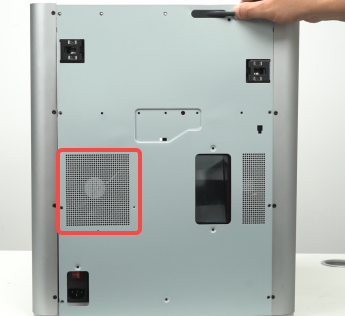
- Exhaust Fan (Back Panel)

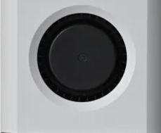
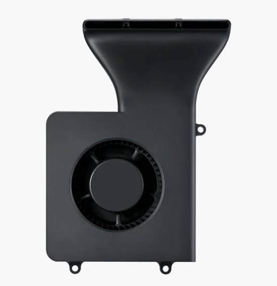
<table id="bkmrk-part-cooling-fan-aux"><thead><tr><td class="align-center">Part cooling fan</td><td class="align-center">Auxiliary part cooling fan</td><td class="align-center">Chamber temperature regulator fan</td></tr></thead><tbody><tr><td class="align-center" style="vertical-align: middle;">![部件冷却风扇.png](https://wiki.bambulab.com/screen-operation/%E9%83%A8%E4%BB%B6%E5%86%B7%E5%8D%B4%E9%A3%8E%E6%89%87.png)</td><td class="align-center" style="vertical-align: middle;">![](https://wiki.bambulab.com/x1/maintenance/replace-aux-fan/new_fan.jpg)</td><td class="align-center" style="vertical-align: middle;">![机箱风扇.png](https://wiki.bambulab.com/screen-operation/%E6%9C%BA%E7%AE%B1%E9%A3%8E%E6%89%87.png)</td></tr></tbody></table>

To open the settings for any of the Fans, press on the name of the fan, where you will then be presented with the controls.

[![Control - Fans.png](https://docs.home.schwetz.au/uploads/images/gallery/2025-05/scaled-1680-/rFlUSFi3omqqYP4F-control-fans.png)](https://docs.home.schwetz.au/uploads/images/gallery/2025-05/rFlUSFi3omqqYP4F-control-fans.png)

Below is the Auxillary Part Cooling Fan controls. Currently the fan is switched off as the slider is grey and the fan speed is at 10%. If the requirement is to run the fan at 100% you can simply press the slider. Otherwise you can hit the + button to select the required speed

[![Control - Fans - Aux Fan - Off.png](https://docs.home.schwetz.au/uploads/images/gallery/2025-05/scaled-1680-/m2XYKRGd7lrRLp3X-control-fans-aux-fan-off.png)](https://docs.home.schwetz.au/uploads/images/gallery/2025-05/m2XYKRGd7lrRLp3X-control-fans-aux-fan-off.png)

Below you can see the Auxillary Part Cooling Fan Settings, Currently the fan is switched on as the slider is green with a tick and the speed is set to 10%

[![Control - Fans - Aux Fan - On.png](https://docs.home.schwetz.au/uploads/images/gallery/2025-05/scaled-1680-/NMmYwhQABGfAI75y-control-fans-aux-fan-on.png)](https://docs.home.schwetz.au/uploads/images/gallery/2025-05/NMmYwhQABGfAI75y-control-fans-aux-fan-on.png)

### Nozzle and Extruder

The Nozzle and Extruder controls allows you to set the

- Nozzle temperature
- Nozzle type and
- Extrude and retract the filament.

To move the filament in the extruder use the up and down arrows. The up arrow will retract the filament (move it away from the hotend, whilst the down arrow will extract (push it through the hotend)

<p class="callout warning">Care is required when retracting the filament, as if you retract too far ( &gt; 18mm) you risk clogging the extruder as you pull hot molten plastic into the extruder.</p>

[![Control - Extruder.png](https://docs.home.schwetz.au/uploads/images/gallery/2025-05/scaled-1680-/kr06gl25xsorIrLR-control-extruder.png)](https://docs.home.schwetz.au/uploads/images/gallery/2025-05/kr06gl25xsorIrLR-control-extruder.png)

To set the extruder temperature click on the button under nozzle temperature. This will then bring up the screen where you can enter the desired temperature.

[![Control - Extruder - Nozzle Temperature.png](https://docs.home.schwetz.au/uploads/images/gallery/2025-05/scaled-1680-/qqjsDGrwWyqVlHN0-control-extruder-nozzle-temperature.png)](https://docs.home.schwetz.au/uploads/images/gallery/2025-05/qqjsDGrwWyqVlHN0-control-extruder-nozzle-temperature.png)

To set the Nozzle Type press the pencil icon next to the nozzle size and type currently installed

[![Extruder - Nozzle Type.png](https://docs.home.schwetz.au/uploads/images/gallery/2025-05/scaled-1680-/7SnG27VozA4kNoiP-extruder-nozzle-type.png)](https://docs.home.schwetz.au/uploads/images/gallery/2025-05/7SnG27VozA4kNoiP-extruder-nozzle-type.png)

### Heatbed

To set the heatbed temperature click on the heatbed button. You will then be prompted to input the temperature.

[![Control - Heatbed.png](https://docs.home.schwetz.au/uploads/images/gallery/2025-05/scaled-1680-/Lgy5yqinBxdZQUuF-control-heatbed.png)](https://docs.home.schwetz.au/uploads/images/gallery/2025-05/Lgy5yqinBxdZQUuF-control-heatbed.png)

<p class="callout info">The maximum temperature that the heatbed can achieve is based on the mains voltage that the machine is using. 120VAC can achieve 120°C whilst 240VAC can achieve 110°C</p>

### Speed

This option will allow you to print the module with the motion settings increased, the speeds settings are below

- **Ludicrous**：166% of normal print speed and acceleration
- **Sport**：124% of normal print speed and acceleration
- **Standard**：normal print speed and acceleration
- **Silent**：50% of normal print speed and acceleration

[![Settings Speed.png](https://docs.home.schwetz.au/uploads/images/gallery/2025-05/scaled-1680-/2Q1tNHYd7VAptUcT-settings-speed.png)](https://docs.home.schwetz.au/uploads/images/gallery/2025-05/2Q1tNHYd7VAptUcT-settings-speed.png)

<p class="callout warning">This setting does not take into account max volumetric rate and does not confirm that the extrusion rates that are being used will be supported by the filament. It is recommended to instead tune your filament profiles to allow you to gain extra speed with confidence that the print will be a success.</p>

### Motion XYZ

This menu allows you to control bothe the toolhead (X,Y) and the headbed (Y).

[![Control - XYZ motion.png](https://docs.home.schwetz.au/uploads/images/gallery/2025-05/scaled-1680-/3kmunZ4gOj7tb91K-control-xyz-motion.png)](https://docs.home.schwetz.au/uploads/images/gallery/2025-05/3kmunZ4gOj7tb91K-control-xyz-motion.png)

#### XY Motion control.

The XY control allows moving the X and Y axis if required, as well as homing the axis. Below is a table that supplies what each of the 9 segments on the graphic do

<table border="1" id="bkmrk-1---move-x-towards-t" style="border-collapse: collapse; width: 100%; height: 290px;"><colgroup><col style="width: 29.642857%;"></col><col style="width: 70.238095%;"></col></colgroup><tbody><tr style="height: 29px;"><td class="align-center" rowspan="9" style="height: 290px; vertical-align: middle;">[![image.png](https://docs.home.schwetz.au/uploads/images/gallery/2025-05/scaled-1680-/GFeWIQlKhbVj0bP9-image.png)](https://docs.home.schwetz.au/uploads/images/gallery/2025-05/GFeWIQlKhbVj0bP9-image.png)

</td><td style="height: 29px;">1 - Move X towards the origin (10 Steps)</td></tr><tr style="height: 29px;"><td style="height: 29px;">2- Move X towards the origin (1 Step)</td></tr><tr style="height: 29px;"><td style="height: 29px;">3 - Move X away from the origin (10 Steps)</td></tr><tr style="height: 29px;"><td style="height: 29px;">4- Move X away from the origin (1 Step)</td></tr><tr style="height: 29px;"><td style="height: 29px;">5 - Move Y away from the origin (10 Steps)</td></tr><tr style="height: 29px;"><td style="height: 29px;">6- Move Y away from the origin (1 Steps)</td></tr><tr style="height: 29px;"><td style="height: 29px;">7- Move Y towards the origin (10 Steps)</td></tr><tr style="height: 29px;"><td style="height: 29px;">8- Move Y towards the origin (1 Step)</td></tr><tr style="height: 29px;"><td style="height: 29px;">9- Home the printer so it knows where the origin exists

  
</td></tr></tbody></table>

<p class="callout danger">Before manually homing or moving the XY axis ensure that nothing remains on the build plate that may foul the toolhead when homing</p>

#### Z-Axis Motion control

The Z-Axes motion controls allow for moving the the headbed up and down in steps of 10 or 1

![image.png](https://docs.home.schwetz.au/uploads/images/gallery/2025-05/scaled-1680-/D5fINLipORF82tVk-image.png)

## Filaments

The filament's allow you to assign, edit and control filaments that are loaded into your printer either via the AMS if fitted or an external spool as well as showing if a filament has been loaded into the extruder. If an AMS is fitted this is where you can

- Observe the filaments loaded including colour and filament type.
- Re-read a RFID Tag
- Unload a filament
- Load a filament
- If a filament is loaded which spool is loaded into the extruder
- If a non Bambu Labs filament has been loaded set all details of the filament
- If a Bambu Labs filament is loaded set the K factor (pressure advance)
- Spools that have a backup spool set for auto refill
- The humidity sensor of each AMS and
- The amount of filament left on the roll.

[![Home - Filament.png](https://docs.home.schwetz.au/uploads/images/gallery/2025-05/scaled-1680-/cehTHkAOdr8skrny-home-filament.png)](https://docs.home.schwetz.au/uploads/images/gallery/2025-05/cehTHkAOdr8skrny-home-filament.png)

### Editing Filaments

There are a few reasons that you mey need to edit a filament, including:

- Using an external spool
- Using a non Bambu Labs spool in the AMS
- Setting a spool to load a pre-saved K Factor on a spool set on the AMS

<p class="callout warning">If a print job is currently in progress you will not be able to edit the filaments until such time as it has finished.</p>

#### AMS

##### Non-Bambu Labs filament.

[![Filament - Edit - Non Bambu.png](https://docs.home.schwetz.au/uploads/images/gallery/2025-05/scaled-1680-/UfJcdbzMqnxaw8r4-filament-edit-non-bambu.png)](https://docs.home.schwetz.au/uploads/images/gallery/2025-05/UfJcdbzMqnxaw8r4-filament-edit-non-bambu.png)

##### Bambu Labs filament.

If you have a bambu labs filamaent with a RFID tag, you will not be able to edit the filaments settings such as colour as this is all done through the QR Code. The only option that you will have is to set the Dynamic Pressure Control

[![Filament - Edit - AMS - Bambu.png](https://docs.home.schwetz.au/uploads/images/gallery/2025-05/scaled-1680-/LwYRohtRjtvzjEJN-filament-edit-ams-bambu.png)](https://docs.home.schwetz.au/uploads/images/gallery/2025-05/LwYRohtRjtvzjEJN-filament-edit-ams-bambu.png)

#### External Spool

<p class="callout info">You do not have to have an external spool currently loaded into the extruder to be able to set the external spool settings, it can be done before or after loading the spool.</p>

To edit the external spool details you need to select the external spool from the list of sources, If you have an AMS this will be to the right of you AMS units on the filament spools and can be identified by the label *"Ext"*. To select it press on the external spool and you will be presented with a screen showing and empty spool.

[![Filament - External = Load.png](https://docs.home.schwetz.au/uploads/images/gallery/2025-05/scaled-1680-/GheqNjhvFtGc4oYj-filament-external-load.png)](https://docs.home.schwetz.au/uploads/images/gallery/2025-05/GheqNjhvFtGc4oYj-filament-external-load.png)

Once the edit dialogue is shown select the:

- Filament Manufacturer
- Filamant Type
- Filament Colour and
- Dynamic Pressure Control profile if created

Once you are happy with the selection, press the confirm button.44

[![Filament - Edit - Non Bambu.png](https://docs.home.schwetz.au/uploads/images/gallery/2025-05/scaled-1680-/UfJcdbzMqnxaw8r4-filament-edit-non-bambu.png)](https://docs.home.schwetz.au/uploads/images/gallery/2025-05/UfJcdbzMqnxaw8r4-filament-edit-non-bambu.png)

Below you can see that the Spool has now changed and shows that red PLA is now shown as the active filament is installed.

[![Filament - External.png](https://docs.home.schwetz.au/uploads/images/gallery/2025-05/scaled-1680-/O7gWmWTMtKcVioiH-filament-external.png)](https://docs.home.schwetz.au/uploads/images/gallery/2025-05/O7gWmWTMtKcVioiH-filament-external.png)

### Loading and Unloading Filaments

#### AMS

<p class="callout info">You can manually load or filament from the AMS if you have the requirement to do so, however, normally this is not required as the correct filament will be loaded and unloaded by the printer.</p>

##### Loading from AMS

You will only be able to load a filament into the extruder, if it is currently empty

[![Home - Filament.png](https://docs.home.schwetz.au/uploads/images/gallery/2025-05/scaled-1680-/cehTHkAOdr8skrny-home-filament.png)](https://docs.home.schwetz.au/uploads/images/gallery/2025-05/cehTHkAOdr8skrny-home-filament.png)

To load an ams filament you need to select the slot that you wish to load and click on the spool picture, this will then highlight the spool by moving it above the others. Select the load button and it will start the process to load the filament into the extruder

[![Filament - AMS - Context.png](https://docs.home.schwetz.au/uploads/images/gallery/2025-05/scaled-1680-/HlbwPJZCC2bm4aiJ-filament-ams-context.png)](https://docs.home.schwetz.au/uploads/images/gallery/2025-05/HlbwPJZCC2bm4aiJ-filament-ams-context.png)
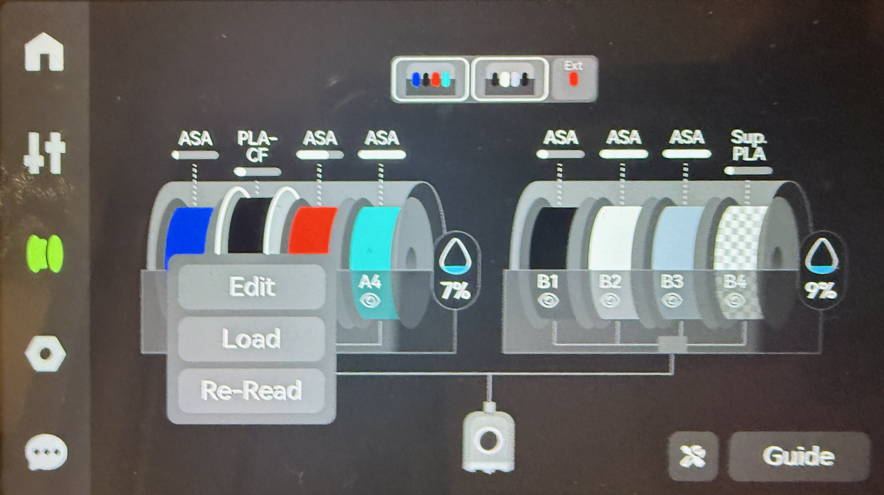
Once this has been completed the loaded filament will be shown by the path from spool to filament being shown. In the example below the Red ASA from B4 has been loaded and is ready for printing to commence.

[![Filament - AMS - Loaded.png](https://docs.home.schwetz.au/uploads/images/gallery/2025-05/scaled-1680-/QP6hvyLzFUNNFGwb-filament-ams-loaded.png)](https://docs.home.schwetz.au/uploads/images/gallery/2025-05/QP6hvyLzFUNNFGwb-filament-ams-loaded.png)

##### Unloading from the AMS

<p class="callout info">You can manually load or filament from the AMS if you have the requirement to do so, however, normally this is not required as the correct filament will be loaded and unloaded by the printer.</p>

To unload a filament that is stored on the AMS you will need to click on the filament to bring up the context menu and select unload,

[![Filament - AMS - Loaded.png](https://docs.home.schwetz.au/uploads/images/gallery/2025-05/scaled-1680-/QP6hvyLzFUNNFGwb-filament-ams-loaded.png)](https://docs.home.schwetz.au/uploads/images/gallery/2025-05/QP6hvyLzFUNNFGwb-filament-ams-loaded.png)

Select the filament spool that you wish to unload, press on the spool and select unload from the context menu.

[![Home - Filament.png](https://docs.home.schwetz.au/uploads/images/gallery/2025-05/scaled-1680-/cehTHkAOdr8skrny-home-filament.png)](https://docs.home.schwetz.au/uploads/images/gallery/2025-05/cehTHkAOdr8skrny-home-filament.png)

#### External Spool

There are many reasons why you may decide to use an external spool, including

- The filament that you are using may not support being loaded from the AMS, for example TPU 85A
- You are doing a quick print job with a filament and you do not want to load it into the AMS
- You are printing from an external dry box
- or an engineering filament that is required to be printed from a blast dryer to avoid moisture

Using a external spool requires additional manual steps that the AMS will perform for you

<p class="callout info">If you find that you have the requirement to commonly need to to print from an external filament source it is recommended to purchase the 4-in-1 PTFE adapter. I highly recommend it's purchase as it will save you from forgetting to re-install your AMS connection on the rear of the printer, hitting print on your next print and coming back hours later to a paused print job. All because you forgot to plug the AMS back into the printer..  
[![image.png](https://docs.home.schwetz.au/uploads/images/gallery/2025-05/scaled-1680-/ns2Z44F5F54tecI0-image.png)](https://au.store.bambulab.com/products/bambu-4-in-1-ptfe-adapter?srsltid=AfmBOoqjGI71NUX1_VmF-A67JGIMs9ShVfIal5DrrGIvuBhdsDdLoZL4)</p>

##### Loading from an External Spool

The process to load an external spool requires the following steps

If not using the 4-in-1 PFTE adapter remove the AMS from the printer input PFTE tube

[![image.png](https://docs.home.schwetz.au/uploads/images/gallery/2025-05/scaled-1680-/ZM2npnRmHFaPamor-image.png)](https://docs.home.schwetz.au/uploads/images/gallery/2025-05/ZM2npnRmHFaPamor-image.png)

Select the external spool as the source of the filament

[![Filament - External.png](https://docs.home.schwetz.au/uploads/images/gallery/2025-05/scaled-1680-/O7gWmWTMtKcVioiH-filament-external.png)](https://docs.home.schwetz.au/uploads/images/gallery/2025-05/O7gWmWTMtKcVioiH-filament-external.png)

Press on the spool and then select the option to load the filament, even though the filament is not currently loaded it will still give you the option to unload it, ensure that you select load.

[![Filament - External - Context Menu.png](https://docs.home.schwetz.au/uploads/images/gallery/2025-05/scaled-1680-/qsTL7CJgKjk7nTuQ-filament-external-context-menu.png)](https://docs.home.schwetz.au/uploads/images/gallery/2025-05/qsTL7CJgKjk7nTuQ-filament-external-context-menu.png)
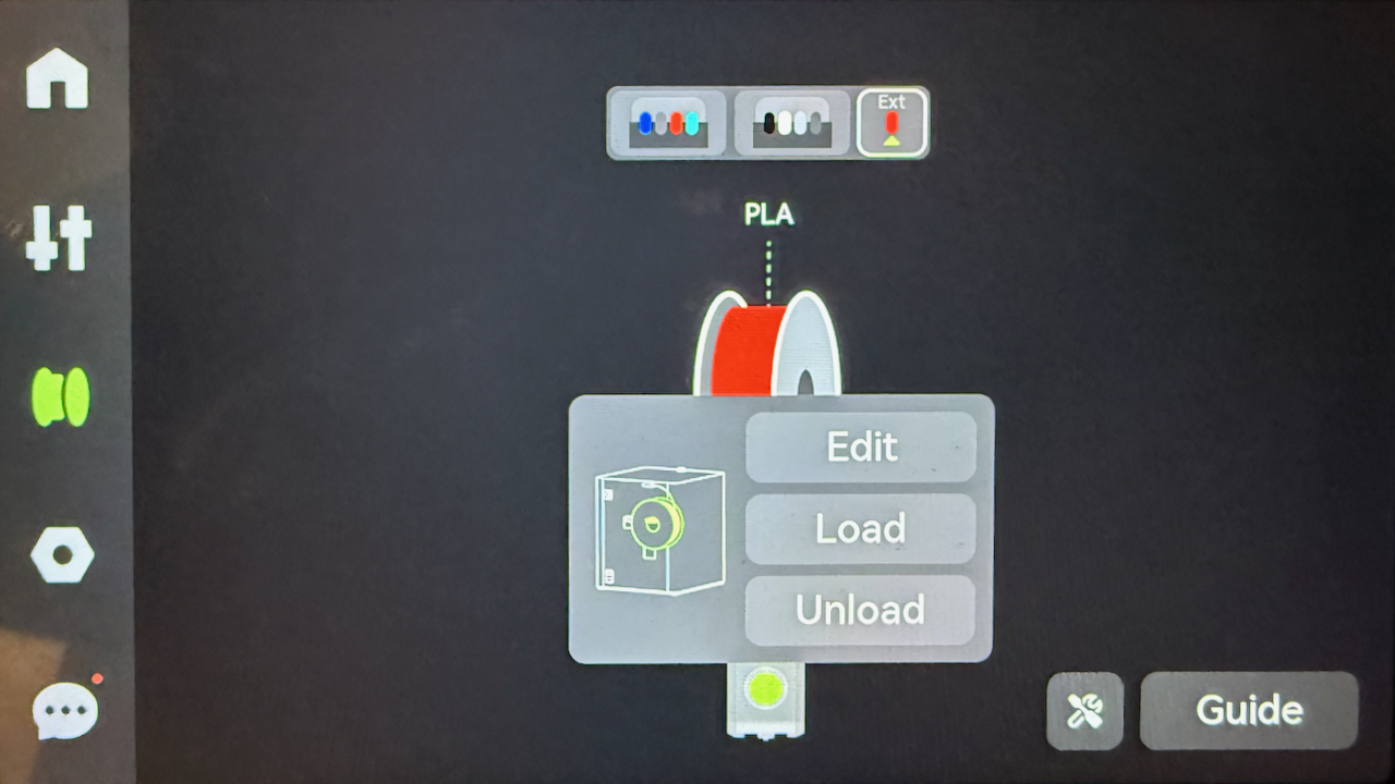
From here the printer will:

- Heat the extruder
- Perform a cut motion
- Move the toolhead to the poop chute and
- Prompt you to manually load the filament

[![Filament - External - Push Filament.png](https://docs.home.schwetz.au/uploads/images/gallery/2025-05/scaled-1680-/1uGVerLGfTZAslOJ-filament-external-push-filament.png)](https://docs.home.schwetz.au/uploads/images/gallery/2025-05/1uGVerLGfTZAslOJ-filament-external-push-filament.png)
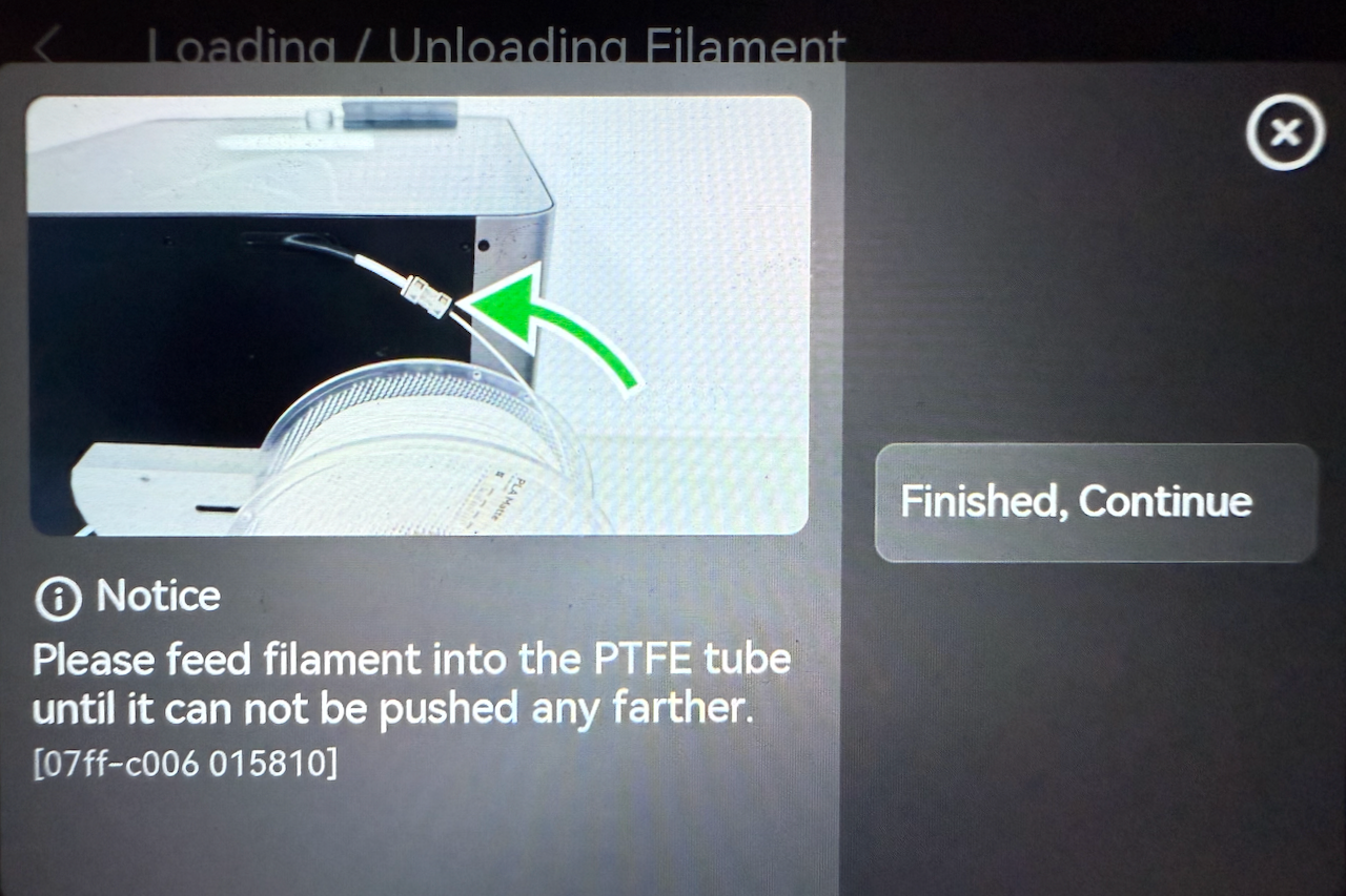
Carefully feed the filament into the input PFTE tube making sure that you do not push too hard and deform the filament. Once the filament has been pushed past the filament sensor you will be prompted to see if the filament has been extruded into the shoot. Keep pressing the *"Not Extruded Yet; Retry"* , whilst gently applying pressure to guide it into the extruder. Once the filament is moving on its own keep pressing the option until you see filament being extruded from the hot-end.

Once this has occurred, press *"Filament Extruded; Continue"*

[![Filament - Load - Extrude.png](https://docs.home.schwetz.au/uploads/images/gallery/2025-05/scaled-1680-/VnwRdioDIhLtrn7W-filament-load-extrude.png)](https://docs.home.schwetz.au/uploads/images/gallery/2025-05/VnwRdioDIhLtrn7W-filament-load-extrude.png)

The printer will then purge out the old filament and prime the nozzle. Once this is completed the printer will then be ready to print from the external spool, and the screen will show the external spool connected to the toolhead.

[![Filament - External - Loaded.png](https://docs.home.schwetz.au/uploads/images/gallery/2025-05/scaled-1680-/Ro8DqTI6BgGBjRqF-filament-external-loaded.png)](https://docs.home.schwetz.au/uploads/images/gallery/2025-05/Ro8DqTI6BgGBjRqF-filament-external-loaded.png)
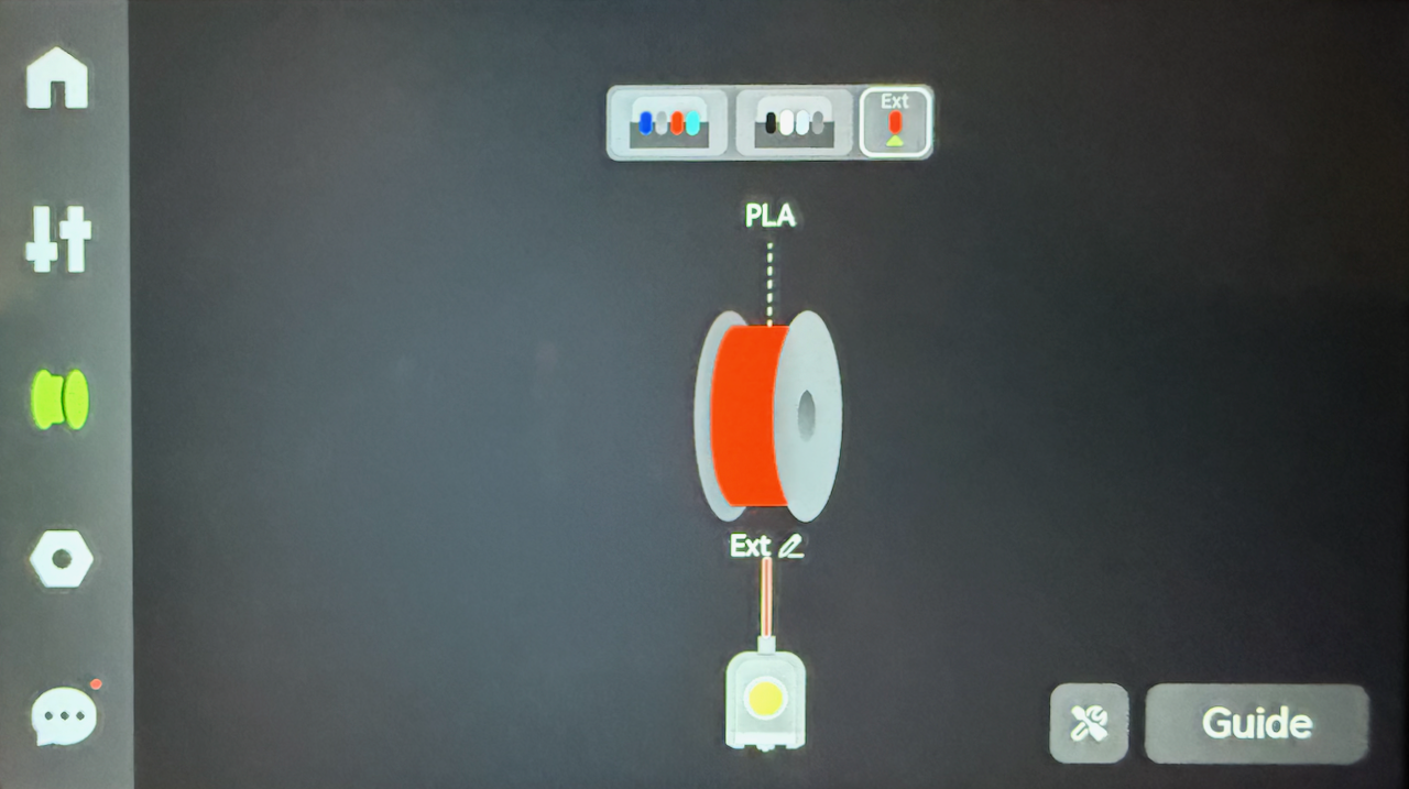
##### Refilling the External Spool

If you are using an external spool and the spool runs out, you need to load a new spool. This is the same process as the load procedure.


##### Unloading the External Spool

<p class="callout info">Once you have unloaded the external spool, the printer will not reset the spool details unless you follow the spool reset steps</p>

To unload the filament, select the external spool if not displayed, and confirm that it currently showing as loaded into the extruder

[![Filament - External - Loaded.png](https://docs.home.schwetz.au/uploads/images/gallery/2025-05/scaled-1680-/Ro8DqTI6BgGBjRqF-filament-external-loaded.png)](https://docs.home.schwetz.au/uploads/images/gallery/2025-05/Ro8DqTI6BgGBjRqF-filament-external-loaded.png)

Press on the spool to bring up the filament, and bring up the context menu and select unload.

[![Filament - External - Context Menu.png](https://docs.home.schwetz.au/uploads/images/gallery/2025-05/scaled-1680-/qsTL7CJgKjk7nTuQ-filament-external-context-menu.png)](https://docs.home.schwetz.au/uploads/images/gallery/2025-05/qsTL7CJgKjk7nTuQ-filament-external-context-menu.png)

From here the printer will:

- Heat the extruder
- Perform a cut motion
- Move the toolhead to the poop chute and
- Prompt you to manually remove the filament

<p class="callout info">Once the the filament is removed the LCD will not still show the filament programmed unless the spool setting are reset</p>

[![Filament - Ext Spool - Unload.png](https://docs.home.schwetz.au/uploads/images/gallery/2025-05/scaled-1680-/oCqY9sM44xJj2nZg-filament-ext-spool-unload.png)](https://docs.home.schwetz.au/uploads/images/gallery/2025-05/oCqY9sM44xJj2nZg-filament-ext-spool-unload.png)

Once the filament out of the filament sensor the printer will update the display to show the extruder is unloaded

[![Filament - External.png](https://docs.home.schwetz.au/uploads/images/gallery/2025-05/scaled-1680-/O7gWmWTMtKcVioiH-filament-external.png)](https://docs.home.schwetz.au/uploads/images/gallery/2025-05/O7gWmWTMtKcVioiH-filament-external.png)

<p class="callout danger">If you are using the 4-in-1 PFTE adapter make sure that you roll the filament back enough that the filament leaves the adapter. Otherwise it will foul the path that a filament from the AMS takes, as once it leaves the filament sensor the printer no longer can detect it</p>

<p class="callout warning">If you have removed the AMS from the back of the printer do not forget to reconnect it before performing your next print.</p>

### Auto Refill

One of the major benefits of using an AMS other than multi-colour printing, is Auto Refill. This allows that if an exact match of a filament (manufacturer, filament type, and colour) to be used if a matching filament spool becomes empty. To confirm that Auto Refill is enabled for a filament.

To bring up the auto refill screen click on the tools button at the bottom right and the select the Auto Refill button.

[![Filament - Autorefill - Menu.png](https://docs.home.schwetz.au/uploads/images/gallery/2025-05/scaled-1680-/XidbvXMmNYjg0kd3-filament-autorefill-menu.png)](https://docs.home.schwetz.au/uploads/images/gallery/2025-05/XidbvXMmNYjg0kd3-filament-autorefill-menu.png)
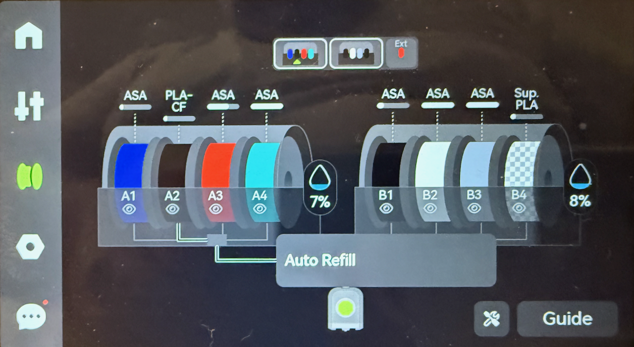
If a filament is matched the screen will show the spools (using slot numbers) to that will be used to refill each other.

<p class="callout warning">When printing with Auto Refill enabled, ensure that you source your print from the spool with less filament available, the slicer and printer otherwise will print with the lowest slot number, even if this is the full spool.</p>

[![Filamant-AutoRefill-Match.png](https://docs.home.schwetz.au/uploads/images/gallery/2025-05/scaled-1680-/QUQf77dUfMoxmrMU-filamant-autorefill-match.png)](https://docs.home.schwetz.au/uploads/images/gallery/2025-05/QUQf77dUfMoxmrMU-filamant-autorefill-match.png)

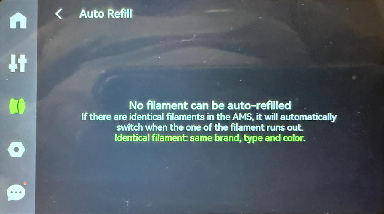
if the printer does not have matching spools then the screen will show that the feature is enabled enable it

[![Filament - Auto Refill - No Match.png](https://docs.home.schwetz.au/uploads/images/gallery/2025-05/scaled-1680-/OUkdJCeckGTaUyhi-filament-auto-refill-no-match.png)](https://docs.home.schwetz.au/uploads/images/gallery/2025-05/OUkdJCeckGTaUyhi-filament-auto-refill-no-match.png)
## Settings

Some, but not all printer settings are able to be configured directly from the printer, but more advanced settings (like the above Auto Refill, can only be configured from either Bambu Studio or Bambu Handy. Others such as binding the printer to your Bambu Labs account you need to use an Applicaton and the Printer.

[![Settings.png](https://docs.home.schwetz.au/uploads/images/gallery/2025-05/scaled-1680-/OcD05gJxxsd1znj7-settings.png)](https://docs.home.schwetz.au/uploads/images/gallery/2025-05/OcD05gJxxsd1znj7-settings.png)

The setting that can be configured from the settings screen are:

- The Account the printer is bound to
- Printer Calibration
- Toolbox and
- Printer Settings

It also provides short cuts to frequently used setting:

- Wifi Settings
- SD Card Settings and
- Firmware

### Account Settings

The account settings can be accessed by clicking on the Account button. Normally the account button will have the avatar of the currently logged in account.

<p class="callout info">The initial binding of the account is done during the printer setup.;</p>

#### Logging out

If you want to rebind the printer to a different account you will need to log out of the current account bound to the printer. This will remove the printer from the bambu account and will need to be rebound to regain access. From here you will also be able to change the Region that your printer is in if you need to move region.

To log out of the bound account click on the log out button

[![Account - Log Out.png](https://docs.home.schwetz.au/uploads/images/gallery/2025-05/scaled-1680-/xBezyJLnmYA0sl0D-account-log-out.png)](https://docs.home.schwetz.au/uploads/images/gallery/2025-05/xBezyJLnmYA0sl0D-account-log-out.png)

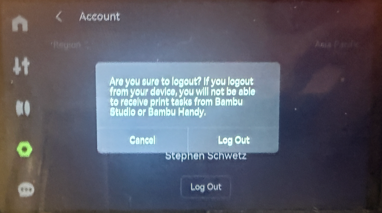
The printer will then prompt you to confirm that you want to log out, Click *"Log Out"* to confirm

[![Account - Log Out - Confirm.png](https://docs.home.schwetz.au/uploads/images/gallery/2025-05/scaled-1680-/vSS3sCwHNLU6wngb-account-log-out-confirm.png)](https://docs.home.schwetz.au/uploads/images/gallery/2025-05/vSS3sCwHNLU6wngb-account-log-out-confirm.png)
#### Binding Printer (Logging In)

If the printer is not bound to an account all online functions from the printer are not enabled until the printer is rebound. To bind the printer involves two steps on the printer screen:

- Select Region
- Scan QR Code with Bambu Handy

The first step is to select the correct region that your printer is installed in. Once you have selected the correct region, press confirm

[![Account - Bind - Region.png](https://docs.home.schwetz.au/uploads/images/gallery/2025-05/scaled-1680-/pk4rdiDIro7AN9gU-account-bind-region.png)](https://docs.home.schwetz.au/uploads/images/gallery/2025-05/pk4rdiDIro7AN9gU-account-bind-region.png)

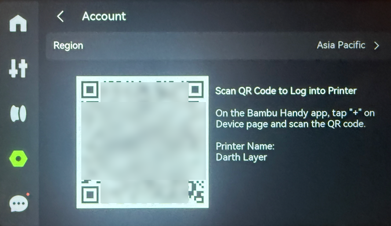
The next screen that is presented will be the QR Code that is required to bind the printer to your Bambu Labs Account.

[![Account - Bind - QR Codes.png](https://docs.home.schwetz.au/uploads/images/gallery/2025-05/scaled-1680-/4FvH1OLqEQAnq1RX-account-bind-qr-codes.png)](https://docs.home.schwetz.au/uploads/images/gallery/2025-05/4FvH1OLqEQAnq1RX-account-bind-qr-codes.png)
For information on the rebinding process is covered in [Binding the Printer](https://docs.home.schwetz.au/books/bambu-labs-x1-carbon/page/binding-the-printer "Binding the Printer")

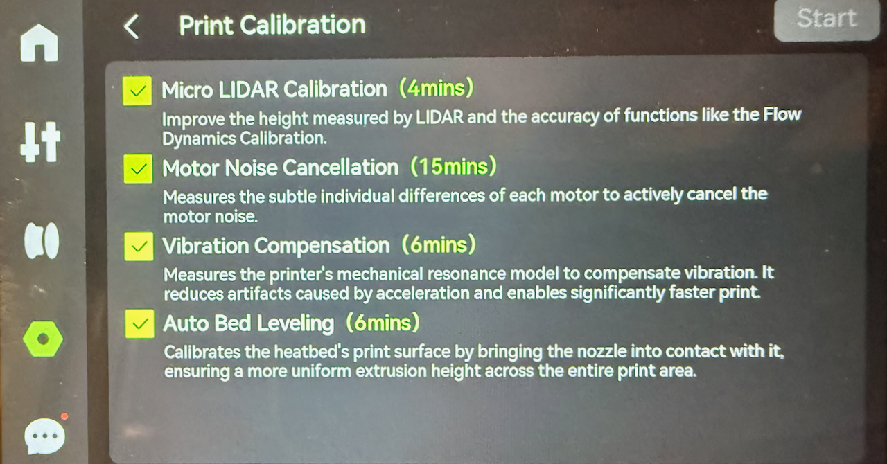
### Print Calibration

Selecting this item allows you to run specific calibration routines which is required when you have replaced parts, performed printer maintenance, or if you notice print quality deteriorating.

You can chose to calibrate

- Bed leveling
- Moror noise calibration
- Micro Lidar calibration and
- Resonance frequency identification

[![Print Calibration.png](https://docs.home.schwetz.au/uploads/images/gallery/2025-05/scaled-1680-/zkfGUlC4Y6YIsJ8d-print-calibration.png)](https://docs.home.schwetz.au/uploads/images/gallery/2025-05/zkfGUlC4Y6YIsJ8d-print-calibration.png)
### Settings

From this screen you will be able to configure the printer and it's attached peripherals including

- Print Options
- AMS Options
- Video Resolution for the chamber camera
- LCD Sleep timout
- Printer Interface Languate
- If the Auxilary Part Cooling Fan is installed
- Device Serial numbers and other system identifiers
- Lan Only mode
- Export a support bundle to the SD-Card and
- Perform a factory reset

<p class="callout info">I am not going to do a deep dive into the settings in this chapter, that wiill be in a later chapter</p>

[![Settings - Page 1.png](https://docs.home.schwetz.au/uploads/images/gallery/2025-05/scaled-1680-/rp2bFMa406m4KaFw-settings-page-1.png)](https://docs.home.schwetz.au/uploads/images/gallery/2025-05/rp2bFMa406m4KaFw-settings-page-1.png)

#### Print options

This option allows you to control the subsystems that are used by the printer whilst it is processing a print job, Including

- AI Print options
- Build Plate Detection
- First Layer Inspection
- Auto Recovery from Step Loss
- Open Door Detection
- Store sent files on External storage

#### AMS Settings

Functions of the AMS system can be controlled through this interface:

- Read filament on insertion
- Read filament on startup
- Remaining filament estimation
- AMS Auto-Refill
- Arrange AMS Order

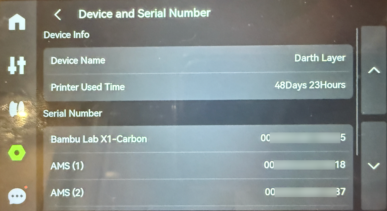
#### Device and Serial Number

This screen allows you to:

- Show and edit the device name
- How long the printer has been used for (cumulative)
- Serial number of the printer
- Serial number of attached items (ams)
- Join the User Experience Improvement Program

[![Settings - Device and Serial Number.png](https://docs.home.schwetz.au/uploads/images/gallery/2025-05/scaled-1680-/KzXrrtBWbKtIurRp-settings-device-and-serial-number.png)](https://docs.home.schwetz.au/uploads/images/gallery/2025-05/KzXrrtBWbKtIurRp-settings-device-and-serial-number.png)
#### Lan Only Mode

<p class="callout warning">This is an advanced setting and should only be turned on if you understand the caviates of using it</p>

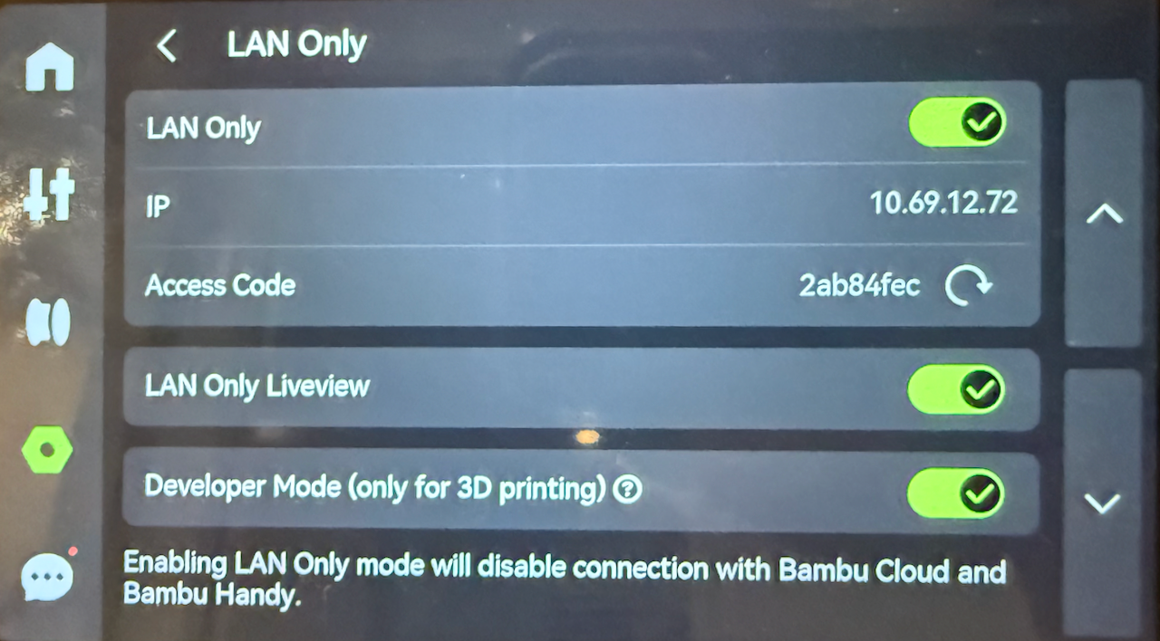
LAN only mode is used for two reasons:

- You do not want the printer communicating with the Bambu Cloud
- You want to use a non bambu product with developer mode to disable authorization controls on the printer

<p class="callout info">Enabling this will stop the printer communicating with the cloud, so you will be unable to use Bambu Handy from the internet.</p>

To turn LAN Only mode on

1. switch the switch on lan only to on
2. the printer will generate the access code
3. the printer will show the IP Address

[![LAN Only Mode.png](https://docs.home.schwetz.au/uploads/images/gallery/2025-05/scaled-1680-/1KhTV6TKiMsThJOr-lan-only-mode.png)](https://docs.home.schwetz.au/uploads/images/gallery/2025-05/1KhTV6TKiMsThJOr-lan-only-mode.png)

You will then be given an option to use developer mode, which allows non-authorised commands to be sent to the printer from a program like Orca Slicer.

[![Lan Only Mode - Enabled.png](https://docs.home.schwetz.au/uploads/images/gallery/2025-05/scaled-1680-/yUSv1KxLMbXpWTOu-lan-only-mode-enabled.png)](https://docs.home.schwetz.au/uploads/images/gallery/2025-05/yUSv1KxLMbXpWTOu-lan-only-mode-enabled.png)
#### Export Logs

Whilst logging a support request for an issue that you are having with your printer, it is recommended to export the support logs and attach them to the job. When exporting files if you are having a printing issues, it is recommended to select all three items. The printer will bundle the files and then encrypt them so that only authorised people will be able to gain access to the logs.

[![Settings-Export Support Log.png](https://docs.home.schwetz.au/uploads/images/gallery/2025-05/scaled-1680-/lT7h1kHUFsTXMqfm-settings-export-support-log.png)](https://docs.home.schwetz.au/uploads/images/gallery/2025-05/lT7h1kHUFsTXMqfm-settings-export-support-log.png)


### Files

The fiiles menu allows you to print models provided by:

- Bambu Studio (Internal)
- Copied to the SD Card and
- Cloud Cache

To access this menu press on the "*Print Files"* menu

#### Internal Files

Internal files are files that are stored in the firmware of the printer. These are files supplied by Bambu Labs to test the accuracy of the printer, tools used in 3d printing and for maintaining the printer.

[![Files - Internal.png](https://docs.home.schwetz.au/uploads/images/gallery/2025-05/scaled-1680-/bLYxoWnGS37t4S1N-files-internal.png)](https://docs.home.schwetz.au/uploads/images/gallery/2025-05/bLYxoWnGS37t4S1N-files-internal.png)

#### SD Card

There are three ways to get files onto the SD Card, you could either

1. Manually copy the file to the SD Card on your computer
2. Enable Cloud File Cache, and this will print all files delivered to the Bambu Cloud Printing Service (Not LAN Mode)
3. If LAN mode is enabled all files are copied to the SD Card

[![Files - SD Card.png](https://docs.home.schwetz.au/uploads/images/gallery/2025-05/scaled-1680-/ODbBXdkJHoq9Sk4O-files-sd-card.png)](https://docs.home.schwetz.au/uploads/images/gallery/2025-05/ODbBXdkJHoq9Sk4O-files-sd-card.png)

#### Printing from the files menu.

To print a file from either the Internal or SD Card select the item from the screen by pressing on the icon and then you will be presented with an option to print a plate from the file before selecting next choose if you want to enable:

- TimeLapse
- Bed Leveling
- Flow Calibration

Unlike with Bambu Studio or Bambu Handy, you can not change the Plate or Nozzle that need to be used, as the file has already been presliced to use the ones preset.

[![Print - Select Plate.png](https://docs.home.schwetz.au/uploads/images/gallery/2025-05/scaled-1680-/F74Mx4LgoIX9Wwb9-print-select-plate.png)](https://docs.home.schwetz.au/uploads/images/gallery/2025-05/F74Mx4LgoIX9Wwb9-print-select-plate.png)

Follow the prompts to select the filaments that you wish to use for the print, Once again you cannot use a different filament type, if the file was sliced for PETG you cannot use PLA to print it. Once you press Next, the file will be sent to be printed

[![Print - Match the Filament.png](https://docs.home.schwetz.au/uploads/images/gallery/2025-05/scaled-1680-/zZfUp19l66swTyr0-print-match-the-filament.png)](https://docs.home.schwetz.au/uploads/images/gallery/2025-05/zZfUp19l66swTyr0-print-match-the-filament.png)

### Toolbox

The toolbox menu is where you will find tools and maintainance options:

- Device Self-test
- Dry Filament
- Carbon Rods Clearance
- Lead Screws Lubrication

[![image.png](https://docs.home.schwetz.au/uploads/images/gallery/2025-05/scaled-1680-/dqKb6gLkxjAWgfnQ-image.png)](https://docs.home.schwetz.au/uploads/images/gallery/2025-05/dqKb6gLkxjAWgfnQ-image.png)

#### Tools

##### Device Self-test

If you are having issues with your printer systems, you can use the device self-test to have the printer ensure that all subsystems are functioning correctly. The Self-test tests the

- Hotend
- Heatbed
- Auto bed leveling
- Vibration compensation

To run a self test click on the self-test and then click on the start button, once this test completes you will be presented with the results.

[![Settings - Device Self-test.png](https://docs.home.schwetz.au/uploads/images/gallery/2025-05/scaled-1680-/yFtP3t52coovDqeZ-settings-device-self-test.png)](https://docs.home.schwetz.au/uploads/images/gallery/2025-05/yFtP3t52coovDqeZ-settings-device-self-test.png)

##### Dry Filament

As the X1C has a heated bed, this can be used to dry filaments if they are too wet to successfully print.

[![Toolbox - Dry Fillament.png](https://docs.home.schwetz.au/uploads/images/gallery/2025-05/scaled-1680-/gcrfwhpENoS7YkL3-toolbox-dry-fillament.png)](https://docs.home.schwetz.au/uploads/images/gallery/2025-05/gcrfwhpENoS7YkL3-toolbox-dry-fillament.png)

#### Maintenance

The printer tracks the period between cleans for both carbon rods and the lead screw calibration

<p class="callout danger">As the printer uses the cloud to provide, you should not rely on this feature if using LAN only mode the printer will not be able to calculate the days remaining correctly.</p>

##### Carbon Rods Clearance

The printer tracks how long it has been since you cleaned the carbon rods. Every time you get a notice to clean the rods, once complete click complete on the screen. to reset the counter.

[![Toolbox - Carbon Rods Clearance.png](https://docs.home.schwetz.au/uploads/images/gallery/2025-05/scaled-1680-/WIH5i7IgVvQDpnBm-toolbox-carbon-rods-clearance.png)](https://docs.home.schwetz.au/uploads/images/gallery/2025-05/WIH5i7IgVvQDpnBm-toolbox-carbon-rods-clearance.png)

##### Lead Screw Lubrication

The printer also tracks the last time that the lead screws have has their grease renewed, ensure once you have lubricated the screws that you reset the counter by clicking complete on this option to reset the counter.

[![Toolbox - Lead Screw Lubrication.png](https://docs.home.schwetz.au/uploads/images/gallery/2025-05/scaled-1680-/PwUeLEFW9F58rqn1-toolbox-lead-screw-lubrication.png)](https://docs.home.schwetz.au/uploads/images/gallery/2025-05/PwUeLEFW9F58rqn1-toolbox-lead-screw-lubrication.png)

### Wireless

The wireless settings are controlled from the WIFI option in settings. From here you can

- Turn Wifi Off/On
- Connect to wireless networks
- Test the network connection.

[![Wifi.png](https://docs.home.schwetz.au/uploads/images/gallery/2025-05/scaled-1680-/vpawpuFLx00gpsJc-wifi.png)](https://docs.home.schwetz.au/uploads/images/gallery/2025-05/vpawpuFLx00gpsJc-wifi.png)

#### Test Network

The test network option allows you to perform a basic check to confirm that the printer can connect to the wireless and to the internet. The test will run showing when each test has been finished and when everything has been tested it will show the results

[![Wireless - Test Network.png](https://docs.home.schwetz.au/uploads/images/gallery/2025-05/scaled-1680-/dqumsxmJ9ayMtZdP-wireless-test-network.png)](https://docs.home.schwetz.au/uploads/images/gallery/2025-05/dqumsxmJ9ayMtZdP-wireless-test-network.png)

### Firmware

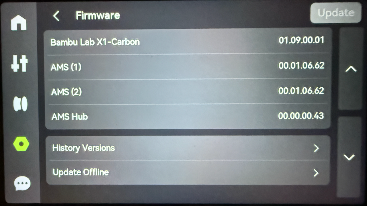
The firmware screen shows the firmware that is installed for each of the device attached to the printer. If there are available firmware updates you can apply them via the Update button.

<p class="callout info">If the update button is green than a update is waiting to be installed.</p>

[![Firmware.png](https://docs.home.schwetz.au/uploads/images/gallery/2025-05/scaled-1680-/Gvb2SpXwntPqbcGL-firmware.png)](https://docs.home.schwetz.au/uploads/images/gallery/2025-05/Gvb2SpXwntPqbcGL-firmware.png)

# Manual Loading / Unloading

<figure class="media" id="bkmrk-"><div class="video-responsive">  
</div></figure>## Steps to load filament

<table border="1" id="bkmrk-set-the-hotend-tempe" style="border-collapse: collapse; width: 100%; height: 1647px;"><colgroup><col style="width: 50%;"></col><col style="width: 50%;"></col></colgroup><tbody><tr style="height: 261px;"><td style="height: 261px;">1. Set the hotend temperature based on the filament you are using, For PLA, a temperature of 220+ ℃ is a good starting point.

</td><td style="height: 261px;"><figure class="image image_resized">![](https://wiki.bambulab.com/x1/manual/loading-filament/set_the_temperature.png)</figure></td></tr><tr style="height: 273px;"><td style="height: 273px;">2\. Wait for the hotend to reach the set temperature

</td><td style="height: 273px;"><figure class="image image_resized">![](https://wiki.bambulab.com/x1/manual/loading-filament/wait_until_the_temperature_is_reached.png)</figure></td></tr><tr style="height: 269px;"><td style="height: 269px;">3. Attach the spool to the back spool holder and cut the filament to a 45-degree angle</td><td style="height: 269px;"><figure class="image image_resized">![](https://wiki.bambulab.com/x1/manual/loading-filament/scr-20220720-htg-2.png)</figure></td></tr><tr style="height: 263px;"><td style="height: 263px;">4. Insert the filament into the back PTFE tube until it reaches the extruder</td><td style="height: 263px;"><figure class="image image_resized">![](https://wiki.bambulab.com/x1/manual/loading-filament/push_the_filament_trough_the_ptfe_tube.png)</figure></td></tr><tr style="height: 319px;"><td style="height: 319px;">5. From the printer screen in the filament tab, click on the rear spool holder to highlight the spool, and click on “Load.” When the pop-up appears, manually push the filament.</td><td style="height: 319px;"><figure class="image image_resized">![](https://wiki.bambulab.com/x1/manual/loading-filament/click-on-load.jpg)</figure></td></tr><tr style="height: 262px;"><td style="height: 262px;">6. Repeat the extrude process until the old filament is purged out, and the new filament color is clear. </td><td style="height: 262px;"><figure class="image image_resized">![](https://wiki.bambulab.com/x1/manual/loading-filament/extrude_until_the_filament_is_clear.png)</figure></td></tr></tbody></table>

<table border="1" id="bkmrk-1.-touch-the%C2%A0setting" style="border-collapse: collapse; width: 100%;"><colgroup><col style="width: 50%;"></col><col style="width: 50%;"></col></colgroup><tbody><tr><td>1\. Touch the **Settings** button on the screen interface, then touch the **Unload** button.

</td><td><figure class="image image_resized">![](https://wiki.bambulab.com/x1/manual/loading-filament/click-on-load.jpg)</figure></td></tr><tr><td>Carefully pull on the filament while also re-spooling it on the filament spool.

</td><td>  
</td></tr><tr><td>  
</td><td>  
</td></tr><tr><td>  
</td><td>  
</td></tr><tr><td>  
</td><td>  
</td></tr><tr><td>  
</td><td>  
</td></tr></tbody></table>

# Multi-Colour Printing Operation Guide

<p class="callout info">When using a 0.2mm nozzle for multi-colour printing, it's important to be aware that the filament switching process may take longer due to the limited maximum volumetric speed. Therefore, it may be necessary to wait for a period of time when changing filaments.</p>

## Load filaments to AMS and configure filament information

Before starting multi-color printing, it is necessary to insert the (AMS) with the filament and set up the filament information. If you are using an official Bambulab filament, the AMS will automatically detect the filament type and color through RFID technology. However, if you are using a third-party filament, you will need to manually configure the relevant information. For details, please refer to AMS setup and loading filament.

## Slicing and sending print jobs in Bambu Studio

Once you have configured the information in the AMS, the next step is to set up and slice the multi-color model in Bambu Studio. For specific colouring and parameter Settings, please refer to Multi-Colour Printing.

**Note: the number in front of each color in Studio is simply the sequential number of the filament, not the AMS slot.**

<figure class="image" id="bkmrk-">![](https://wiki.bambulab.com/x1/manual/muti-color-print/%E9%A2%9C%E8%89%B2%E5%89%8D%E7%9A%84%E7%BC%96%E5%8F%B7en.png)</figure>When printing from Bambu Studio, it will automatically assign the closest color to each filament based on the filament type. However, you have the option to manually modify the color assignments if needed.

Before sending the print job, it's important to carefully review the pop-up window to ensure that the selected slots for each color match your expectations. If a slot displays a "?", it indicates that a third-party filament is being used and the filament information has not been configured. Nonetheless, you can still select that slot for printing, but please ensure that the filament in that slot matches the type selected during slicing.

<figure class="image" id="bkmrk--1">![](https://wiki.bambulab.com/software/bambu-studio/filaments/manual_mapping.png)</figure><figure class="image image_resized" id="bkmrk--2">![](https://wiki.bambulab.com/x1/manual/muti-color-print/%E6%98%A0%E5%B0%84%E6%8C%87%E5%8D%97en.png)</figure>## Start the print job from the SD card

If you are starting a print job using the SD card, there is no need to pre-select the AMS slot information during the slicing process in Bambu Studio. Instead, you can simply slice the model and import the sliced file directly to the SD card.

After selecting the printed file on the SD card, it will first automatically map the slot that matches the filaments of the same kind with the closest color, as shown in the figure below:

<figure class="image image_resized" id="bkmrk--3">![](https://wiki.bambulab.com/x1/manual/muti-color-print/%E5%B1%8F%E5%B9%95%E4%B8%8A%E8%87%AA%E5%8A%A8%E6%98%A0%E5%B0%84en.png.jpg)</figure>If you wish to modify the mapping of colors, you can manually select the corresponding slots for each color on the screen.

<figure class="image image_resized" id="bkmrk--4">![](https://wiki.bambulab.com/x1/manual/muti-color-print/%E5%B1%8F%E5%B9%95%E4%B8%8A%E6%89%8B%E5%8A%A8%E9%80%89%E6%8B%A9%E6%8F%92%E6%A7%BDen.png)</figure>If the filament type used for slicing does not match the filament type recognized by the AMS, you will not be able to select that filament for printing. In the example figure below, you can see that PLA slice files can be selected for printing using AMS slots 1, 2, and 4, but ABS in slot 3 cannot be selected.

<figure class="image image_resized" id="bkmrk--5">![](https://wiki.bambulab.com/x1/manual/muti-color-print/%E6%9D%90%E6%96%99%E4%B8%8D%E5%90%8C%E4%B8%8D%E5%8F%AF%E9%80%89%E6%8B%A9en.png)</figure>## Print built-in models

Printing the printer's built-in model indeed has some special considerations. Currently, it only supports printing from the first slot, and manual selection of slots is not possible. Instead, you need to place the filaments according to the sequence prompted on the screen. The specific instructions and prompts can be found on the preparation page.

<figure class="image image_resized" id="bkmrk--6">![](https://wiki.bambulab.com/x1/manual/muti-color-print/%E5%86%85%E7%BD%AE%E6%A8%A1%E5%9E%8B%E5%B1%8F%E5%B9%95%E6%8F%90%E7%A4%BAen.png)</figure>

# Initial Printer Setup

After you unbox your brand new X1 3D printer, you need to go through the initial setup process. Here's how to do it:

<figure class="media" id="bkmrk-"><div class="video-responsive"></div></figure><table border="1" id="bkmrk-the-first-step-is-to" style="border-collapse: collapse; width: 100%; height: 1220px;"><colgroup><col style="width: 50%;"></col><col style="width: 50%;"></col></colgroup><tbody><tr style="height: 276px;"><td style="height: 276px;">The first step is to select your language,</td><td style="height: 276px;"><figure class="image">![](https://wiki.bambulab.com/x1/manual/select_the_language.png)</figure></td></tr><tr style="height: 267px;"><td style="height: 267px;">Select your Wi-Fi network. Enter your credentials and after connecting, tap the Next button</td><td style="height: 267px;"><figure class="image">![](https://wiki.bambulab.com/x1/manual/select_your_wi-fi_network.png)</figure></td></tr><tr style="height: 282px;"><td style="height: 282px;">Scan the QR Code in Bambu Handy</td><td style="height: 282px;"><figure class="image">![](https://wiki.bambulab.com/x1/manual/scan_the_qr_code_to_bind_the_printer.png)</figure></td></tr><tr style="height: 279px;"><td style="height: 279px;">Accept the Terms and Conditions</td><td style="height: 279px;"><figure class="image">![](https://wiki.bambulab.com/x1/manual/agree_with_the_terms_and_conditions.png)</figure></td></tr><tr style="height: 29px;"><td style="height: 29px;">You can choose to join the improvement program, which can help to improve the printer. Tap Join if you want to help, or Skip if you don't want to join the program. </td><td style="height: 29px;"><figure class="image">![](https://wiki.bambulab.com/x1/manual/join_the_feedback_program.png)</figure></td></tr><tr style="height: 29px;"><td style="height: 29px;">Start the calibration process. Tap Next to get started.</td><td style="height: 29px;"><figure class="image">![](https://wiki.bambulab.com/x1/manual/start_the_calibration_process.png)</figure></td></tr><tr style="height: 29px;"><td style="height: 29px;">Tap the Calibrate button to start the automated calibration procedure</td><td style="height: 29px;"><figure class="image image_resized">![](https://wiki.bambulab.com/x1/manual/calibrate_the_printer.png)</figure></td></tr><tr style="height: 29px;"><td style="height: 29px;">The printer will start the calibration procedure. You might hear loud vibration noises. They are normal. </td><td style="height: 29px;"><figure class="image image_resized">![](https://wiki.bambulab.com/x1/manual/the_printer_is_calibrating.png)</figure></td></tr><tr><td>When the calibration is complete, the following message will appear on the screen</td><td><figure class="image image_resized">![](https://wiki.bambulab.com/x1/manual/initialization_complete.png)</figure></td></tr></tbody></table>

.

# Specifications

<table border="1" id="bkmrk-item-specification-x" style="border-collapse: collapse; width: 100%; height: 293.65625px;"><colgroup><col style="width: 33.333333%;"></col><col style="width: 33.333333%;"></col><col style="width: 33.333333%;"></col></colgroup><tbody><tr style="height: 29px;"><td class="align-center" colspan="2" rowspan="2" style="height: 58px; background-color: rgb(236, 240, 241); vertical-align: middle;">**Item**  
</td><td class="align-center" style="height: 29px; background-color: rgb(236, 240, 241);">**Specification**</td></tr><tr style="height: 29px;"><td class="align-center" style="height: 29px;"> **X1-Carbon**  
</td></tr><tr style="height: 29px;"><td class="align-center" colspan="2" style="height: 29px;">Printing Technology  
</td><td class="align-center" style="height: 29px;">Fused Deposition Modeling</td></tr><tr style="height: 32.65625px;"><td class="align-center" style="height: 32.65625px;">Body</td><td class="align-center" style="height: 32.65625px;">Build Volume(W\*D\*H)</td><td class="align-center" style="height: 32.65625px;">256\*236\*256 mm<sup>3</sup></td></tr><tr style="height: 29px;"><td class="align-center" style="height: 29px;">  
</td><td class="align-center" style="height: 29px;">Chassis</td><td class="align-center" style="height: 29px;">Steel</td></tr><tr style="height: 29px;"><td class="align-center" style="height: 29px;">  
</td><td class="align-center" style="height: 29px;">Shell</td><td class="align-center" style="height: 29px;">Aluminium and Glass</td></tr><tr style="height: 29px;"><td class="align-center" style="height: 29px;">  
</td><td class="align-center" style="height: 29px;">  
</td></tr><tr style="height: 29px;"><td class="align-center" style="height: 29px;">  
</td><td class="align-center" style="height: 29px;">  
</td></tr><tr style="height: 29px;"><td class="align-center" style="height: 29px;">  
</td><td class="align-center" style="height: 29px;">  
</td></tr><tr style="height: 29px;"><td class="align-center" style="height: 29px;">  
</td><td class="align-center" style="height: 29px;">  
</td></tr></tbody></table>

# Automated Material System

# Introduction to AMS

## **How does AMS work?**

The AMS consists of three major parts: a set of four **Filament Slots**, a **Filaments Hub**, and a **Filament Buffer**. Each **Filament Slot** has its own motor to actively push the filament forward or rewind it to the spool. The **Filament Hub** merges four filament paths into one and gives the filament a second-stage driving force with a brushless motor. The **Filament Buffer** is located at the back of the printer, which connects the AMS to the tool head extruder, in order to ensure the tension on the filament is within a given range so that the tool head extruder can work easily and precisely.   
  
In total, there are 10 sensors integrated into the filament path, meticulously monitoring and controlling the position, speed, and tension of the filament.

<figure class="table" id="bkmrk-"><table><tbody><tr><td><figure class="image image_resized">![](https://wiki.bambulab.com/x1/manual/intro-ams/ams-photo.jpg)</figure></td><td><figure class="image">![](https://wiki.bambulab.com/x1/manual/intro-ams/ams-lid-size1.png)</figure></td></tr></tbody></table>

</figure>## **Internal Components**

### **Filament Slot** 

The AMS has 4 filament slots, each filament slot has its own motor and gears to actively push the filament forward or wind it back to the spool. Each filament slot also has a sensor to detect the filament, when a filament is inserted, it will pull the filament automatically. During this process, it pulls the filament just like an extruder. When it needs to wind the filament back, it also rotates the spool for filament winding.

<figure class="image" id="bkmrk--1">![](https://wiki.bambulab.com/x1/manual/intro-ams/filament-slots.jpg)</figure>### **Filaments Hub** 

The **Filaments Hub** is located at the bottom of AMS, it consists of four hall sensors, one magnetic rotary encoder, and one brushless motor. It merges four filament paths into one. The hall sensor detects when the filament has reached a specific location, which in turn activates the brushless motor to give the filament a second stage driving force.

<figure class="image" id="bkmrk--2">![](https://wiki.bambulab.com/x1/manual/intro-ams/filament-hub.jpg)</figure>#### **RFID system**

The **RFID System** can automatically identify the RFID tag on the Bambulab filament spools, which can then sync the filament information to the Bambulab slicer (Bambu Studio).

<figure class="image image_resized" id="bkmrk--3">![](https://wiki.bambulab.com/x1/manual/intro-ams/rfid-antenna.png)</figure>#### **Moisture-proof System** 

The **Moisture-proof System** consists of a humidity sensor, two packets of desiccant, and silicon rubber O-rings. The desiccant can absorb moisture to keep the air in the AMS dry. The silicon rubber O-rings are installed to make sure the AMS remains airtight in order to avoid ruining your hygroscopic filaments. When the air humidity exceeds the standard preset in the AMS, the humidity sensor \[under development\] will detect and remind the user to replace the desiccant bags.

<figure class="image image_resized" id="bkmrk--4">![](https://wiki.bambulab.com/x1/manual/intro-ams/moisture-proof-system.jpg)</figure>## External Components

The AMS needs to either be paired with a filament buffer (single AMS) or an AMS Hub (Multiple AMS)

### **Filament Buffer** 

<figure class="image image_resized" id="bkmrk--5">![](https://wiki.bambulab.com/x1/manual/intro-ams/filament-buffer.png)</figure>The Filament Buffer is located at the back of the printer, connected to both the AMS and the toolhead extruder. It has a slide, a spring, and a hall sensor. When the AMS pushes the filament into the toolhead extruder, the slide will move forward due to the pressure of the filament. The hall sensor can then detect the displacement and location of the slide, and feedback that signal back to the AMS and the printer. By controlling the feed speed of the AMS, we can make sure the tension on the filament is within a given range so that the toolhead extruder can work easily and precisely, without adding too much or too little tension.

### **AMS Hub** 

<figure class="image image_resized" id="bkmrk--6">![](https://wiki.bambulab.com/x1/manual/intro-ams/ams-hub.png)</figure>The **AMS Hub** replaces the filament Buffer. It allows the user to connect four AMS units, which in turn can supply 16 different filament spools to the printer. The AMS Hub is composed of a filament selection module and a buffer module. The filament selection module has four inlets to connect to four separate AMS units. Each slot has a hall sensor to detect the filament. The buffer module’s function is the same as it is with the standard filament buffer, it has a slide, a spring, and a hall sensor to make sure the tension on the filaments is within a given range.

<p class="callout warning">The AMS only supports spools with a width of 50-68mm and a diameter of 197-202mm.</p>

<p class="callout danger">It is recommended to not use cardboard spools without plastic adapter rings as they can slip and as the cardboard wears the scarf can clog the workings of the AMS</p>

<p class="callout danger">Do not load soft materials like TPU (excluding TPU for AMS) and damp PVA into the AMS, as the functioning of the AMS can cause these to break within the AMS and Filament Buffer or AMS Hub.</p>

# Introduction to AMS2 Pro


# New Page


# New Page


# Optional Accessories

### PTFE adapter

PTFE tube can connect 4 feed tubes to the printer at the same time. When connecting multiple AMS 2 Pro to H2 series printers, the PTFE adapter is required.
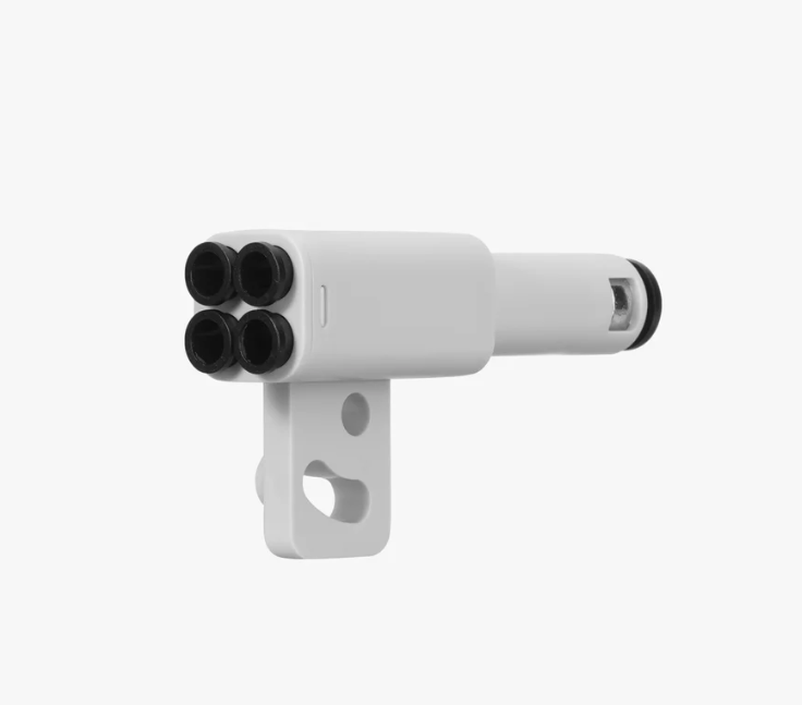
![](https://wiki.bambulab.com/ams-2-pro/manual/part-intro-and-connection-guide/en/image-17.png)

# Introduction to HMS2 HT


# Connecting AMS to the Printer

## Single AMS Setup

<table border="1" id="bkmrk-ake-the-ptfe-tube-fr"><colgroup><col></col><col></col></colgroup><tbody><tr><td>Take the PTFE tube from inside the AMS unit, and connect it from the blue PTFE coupler on the machine to the filament buffer in the back.

</td><td><figure contenteditable="false">![](https://wiki.bambulab.com/x1/manual/connect-ams/step-1-connect-ptfe-blue-coupler-to-filament-buffer.png)</figure><figure contenteditable="false">![](https://wiki.bambulab.com/x1/manual/connect-ams/check_buffer_spring.png)<figcaption contenteditable="true"><p class="callout warning">Make sure the spring of the buffer is not stuck</p>

</figcaption></figure></td></tr><tr><td>Take the PTFE tube which is already connected to the AMS unit, and connect it to the left side of the filament buffer.

</td><td><figure contenteditable="false">![](https://wiki.bambulab.com/x1/manual/connect-ams/step-2-ptfe-from-ams-to-left-filament-buffer.png)</figure></td></tr><tr><td>Connect the four-pin cable to the connector located at the bottom of the filament buffer, then proceed to connect it to the printer as shown below.

</td><td><figure contenteditable="false">![](https://wiki.bambulab.com/x1/manual/connect-ams/step-3-connect-fourpin-under-filament-buffer-into-port.png)</figure><p class="callout danger">Note: Do not insert the 4-pin cable in the wrong direction. If you are using an L-shaped plug cable, pay attention to the text prompts on it. If you insert the 4-pin cable in the wrong direction, it may cause the printer and AMS mainboard to burn down.</p>

<figure contenteditable="false">![](https://wiki.bambulab.com/x1/manual/connect-ams-hub/4p_dir.png)</figure>[![image.png](https://docs.home.schwetz.au/uploads/images/gallery/2025-05/scaled-1680-/vQ3Lwiok8evTqi5y-image.png)](https://docs.home.schwetz.au/uploads/images/gallery/2025-05/vQ3Lwiok8evTqi5y-image.png)

</td></tr><tr><td>  
</td><td><figure contenteditable="false">![](https://wiki.bambulab.com/x1/manual/connect-ams/step-4-connect-to-first-port-on-ams.png)</figure></td></tr><tr><td>Connect the six-pin cable to the first connector on the AMS, and the other side needs to be connected to the connector located on the left side of the filament buffer.

</td><td>[![image.png](https://docs.home.schwetz.au/uploads/images/gallery/2025-05/scaled-1680-/gx8YTf6ufkYbbJz6-image.png)](https://docs.home.schwetz.au/uploads/images/gallery/2025-05/gx8YTf6ufkYbbJz6-image.png)

[![image.png](https://docs.home.schwetz.au/uploads/images/gallery/2025-05/scaled-1680-/BHjvkDBi6mVdoPdM-image.png)](https://docs.home.schwetz.au/uploads/images/gallery/2025-05/BHjvkDBi6mVdoPdM-image.png)

<figure contenteditable="false">![](https://wiki.bambulab.com/x1/manual/connect-ams/step-4-connect-to-leftside-of-filament-buffer.png)</figure>[![image.png](https://docs.home.schwetz.au/uploads/images/gallery/2025-05/scaled-1680-/eyhdbqDiLnhnNNlv-image.png)](https://docs.home.schwetz.au/uploads/images/gallery/2025-05/eyhdbqDiLnhnNNlv-image.png)

<p class="callout warning">If the spool holder is installed, place the PTEF tube under the holder to reduce resistance of loading/unloading</p>

</td></tr></tbody></table>

## Multi AMS Setup

### Filament Buffer and AMS Hub

The built-in Filament Buffer of the printer can only be connected to 1 AMS. When replaced with AMS Hub, the printer will be able to connect up to 4 AMS.

<figure class="image image_resized" id="bkmrk-">![](https://wiki.bambulab.com/ams/ams-hub/buffer_hub.jpg)</figure>### Connect AMS Hub and multi-AMS

<table border="1" id="bkmrk-please-remove-the-bu" style="border-collapse: collapse; width: 100%;"><colgroup><col style="width: 35.238095%;"></col><col style="width: 64.642857%;"></col></colgroup><tbody><tr><td>Please remove the buffer from the back of the printer (if applicable) and install the AMS Hub, as shown in the image below. Once the AMS Hub has been installed, proceed to connect the PTFE tube from the Hub to the PTFE coupler.</td><td><figure class="image image_resized">![](https://wiki.bambulab.com/x1/manual/connect-ams-hub/ptfe_couple.jpg)</figure></td></tr><tr><td>Please ensure that the PTFE tube runs under the spool holder and not over, as shown in the image below. </td><td><figure class="image image_resized">![](https://wiki.bambulab.com/x1/manual/connect-ams-hub/avoid_ptfe_from_touching_spool_holder.png.jpg)</figure><p class="callout warning">Please ensure that the PTFE tube runs **under** the spool holder and not over, as shown in the image below. </p>

<figure class="image image_resized">![](https://wiki.bambulab.com/x1/manual/connect-ams-hub/check_if_spring_stuck.png.jpg)</figure><p class="callout warning">The spring within the AMS Hub should not be stuck/compressed. Please ensure that it moves freely within the AMS Hub.</p>

</td></tr><tr><td>Connect the AMS Hub to the printer with the Bambu Bus Cable 4 pin.</td><td><figure class="image image_resized">![](https://wiki.bambulab.com/x1/manual/connect-ams-hub/4p_dir.png)<figcaption><p class="callout danger">When connecting the 4 pin cable, make sure it is in the correct orientation. If you are using an L-shaped plug cable, pay attention to its text prompts. If you insert the 4 pin cable in the wrong direction, it may cause the printer and AMS mainboard to burn down</p>

<figure class="image image_resized">![](https://wiki.bambulab.com/x1/manual/connect-ams-hub/l%E5%9E%8B%E6%8F%92%E5%A4%B4.png)<figcaption></figcaption></figure></figcaption></figure></td></tr><tr><td>Connect AMS to the AMS hub

</td><td><figure class="image image_resized">![](https://wiki.bambulab.com/x1/manual/connect-ams-hub/cable_connect_and_id.png)</figure></td></tr><tr><td>Connect the most frequently used AMS to the AMS Hub and power on the printer. Then, connect the remaining AMS to the other Bus Cable 6 pin port of the previous AMS.

Kind reminder:   
Our store offers two types of 6-pin bus cables: 510 mm and 1500 mm in length. The 510 mm cable is commonly used for connecting the buffer and AMS, while the 1500 mm cable is widely used for connecting the AMS Hub and AMS.

</td><td><figure class="image image_resized">![](https://wiki.bambulab.com/x1/manual/connect-ams-hub/multi_ams_and_hub_connect.jpg)</figure><p class="callout info">Having the correct PTFE Tube length is important. We recommend keeping it as short as possible while avoiding excessive bending. This helps minimize AMS feed resistance and reduces the time required for filament loading and unloading.</p>

<p class="callout danger">Note: When connecting multiple AMS to the AMS Hub, it is advised to keep the longest PTFE tube length within 3.5 meters. Excessive length in the feeding path can result in increased resistance, potentially affecting the smooth loading and unloading of filament. Additionally, avoid excessive bending of the PTFE tube to minimize resistance.</p>

</td></tr><tr><td>Please check your printer to ensure the correct installation of the AMS Hub and additional AMS units. Refer to the provided image for a successful setup.</td><td><figure class="image image_resized">![](https://wiki.bambulab.com/x1/manual/connect-ams-hub/check_the_connection.jpg)</figure></td></tr></tbody></table>

### AMS ID assignment

Each AMS is assigned an ID, which is displayed on the screen. The logic for assigning AMS ID is to easily identify the connection between them, e.g., AMS1 is directly connected to the AMS Hub, AMS2 is connected to AMS1, and so on.

**Please note that you should connect them individually to be able to assign the ID in order. <u>Keep the printer powered on during this process.</u>**  
  
**However, if you connect multiple AMS units in advance and then connect to the AMS Hub at the end, or you connect all AMS to the hub before powering on the printer, it will randomly assign IDs to these AMS.**

<table border="1" id="bkmrk-ams-1-connects-to-th" style="border-collapse: collapse; width: 100%;"><colgroup><col style="width: 50%;"></col><col style="width: 50%;"></col></colgroup><tbody><tr><td>  
</td><td><figure class="image">![](https://wiki.bambulab.com/x1/manual/connect-ams-hub/assign_ams_id.png)<figcaption>AMS 1 connects to the AMS Hub, and then AMS 2 connects to AMS 1</figcaption></figure></td></tr><tr><td>  
</td><td><figure class="image image_resized">![](https://wiki.bambulab.com/x1/manual/connect-ams-hub/ams_id.png)</figure></td></tr></tbody></table>

## How to Reassign the AMS ID

The AMS ID will be saved and not cleared even if the machine is turned off. You can reset the AMS ID as shown below, **please disconnect the AMS cable after clicking this button**.

<figure class="image image_resized" id="bkmrk--1">![](https://wiki.bambulab.com/x1/manual/release-note/u3/%E9%87%8D%E7%BD%AEams_id_en.png)</figure><figure class="image image_resized" id="bkmrk--2"><figcaption></figcaption></figure>

# Bambu Studio

# Filaments

# 3D Filaments for Beginners

When starting on your 3d printing journey you will be overwelmed with choices on filament that is available on the market, these range from basic to engineering filaments, and you need to resist the urge to move to more advanced filaments before you have learnt the concepts and craft of 3d printing, otherwise, you will not get the benefit of the properties the more advanced filamants

## What is the best filaments.

Regardless of the type of filament that you are looking at using, you get what you pay for. I always use Bambu Lab's own filaments, because they are good quality, are delivered rapidly and are free of moisture out of the packet. However, this is only because Bambu have a presence in Australia. The other reason for use is the ease of use that comes with using filaments with NFC tags when using them with AMS.

However, if it is not price competative for you to use manufacture filaments

# Advanced Topics

# X1C Specific G-Code

Bambu Labs has partially implemented [Marlin G-Code](https://marlinfw.org/docs/gcode/G000-G001.html) commands and have added their own custom G-Code commands to perform functions that are not implemented in Marlin. It is also important to note that the X1C runs their own G-Code engine and does not use the open-source Marlin Firmware on their MC Board.

## Hardware Control

### Printer

<table border="1" id="bkmrk-code-description-exa" style="width: 100%; border-collapse: collapse; border-style: solid; height: 5114.1875px; border-width: 1px;"><thead><tr style="height: 29px;"><th style="width: 18.712753%; height: 29px;">**Code**</th><th style="width: 40.882002%; height: 29px;">**Description**</th><th style="width: 40.405244%; height: 29px;">**Example**</th></tr></thead><tbody><tr style="height: 72px;"><td style="width: 18.712753%; height: 72px;">G29.1</td><td style="width: 40.882002%; height: 72px;">Set Z-trim value to #

<p class="callout info">Use 0 to clear Z-trim</p>

</td><td style="width: 40.405244%; height: 72px;">Squish for Textured PEI

```G-Code
G29.1 Z-0.04
```

</td></tr><tr style="height: 141.1875px;"><td style="width: 18.712753%; height: 141.1875px;">G29.2 </td><td style="width: 40.882002%; height: 141.1875px;">Bed leveling compensation (ABL)</td><td style="width: 40.405244%; height: 141.1875px;">Disable ABL

```G-Code
G29.2 S0
```

Enable ABL

```G-Code
G29.2 S1
```

</td></tr><tr style="height: 45px;"><td style="width: 18.712753%; height: 45px;"> G29.4</td><td style="width: 40.882002%; height: 45px;"> High frequency z compensation</td><td style="width: 40.405244%; height: 45px;"> Turn off high frequency z compensation

```
G29.4 S0
```

Turn on high frequency z compensation

```G-Code
G29.4 S1
```

</td></tr><tr style="height: 45px;"><td style="width: 18.712753%; height: 45px;">M205 </td><td style="width: 40.882002%; height: 45px;">Sets the jerk limits in mm/sec for the X Y Z and E motions

<p class="callout info">If you are not chainging an jerk limit axis you do not need to explicity list it</p>

</td><td style="width: 40.405244%; height: 45px;">```
M205 X0.5 Y1.01 Z2.02 E3.03
```

  
</td></tr><tr style="height: 105px;"><td style="width: 18.712753%; height: 105px;">M17 X/Y/Z#.#</td><td style="width: 40.882002%; height: 105px;">Set X/Y/Z Stepper Motor Current

<p class="callout danger">Be EXTREMELY careful using this command as it is VERY EASY to cause hardware damage with it should you set it too high!!!</p>

</td><td style="width: 40.405244%; height: 105px;">set Z stepper current to 0.4 Amps

```G-Code
M17 Z0.4
```

</td></tr><tr style="height: 289px;"><td style="width: 18.712753%; height: 289px;">M106 P1 S0-255</td><td style="width: 40.882002%; height: 289px;">Part cooling fan off-full\*\*\*</td><td style="width: 40.405244%; height: 289px;">Sets the part fan on at 70%

```G-Code
M106 P1 S180
```

Sets the Aux fan on at 100%

```G-Code
M106 P2 S255
```

Sets the chamber fan on at 0%

```
M106 P3 S0
```

Sets the part fan on at 70%

```
M106 A1 S180
```

</td></tr><tr style="height: 98px;"><td style="width: 18.712753%; height: 98px;">M142</td><td style="width: 40.882002%; height: 98px;">Chamber Fan Temp Control</td><td style="width: 40.405244%; height: 98px;">Set chamber fan to min start rpm @35° and ramp to full speed at 40°

```G-Code
M142 P1 R35 S40
```

</td></tr><tr style="height: 82px;"><td style="width: 18.712753%; height: 29px;">M400</td><td style="width: 40.882002%; height: 29px;">Pause </td><td style="width: 40.405244%; height: 29px;">Pause until all movement completes

```
M400
```

Pause for 10 seconds

```G-Code
M400 S10
```

 Pause for User Interaction

```
M400 U1
```

 Pause for 500 miliseconds

```G-Code
M400 P500
```

</td></tr><tr style="height: 82px;"><td style="width: 18.712753%; height: 82px;">M220</td><td style="width: 40.882002%; height: 82px;">Set feed rate to percent of normal.

<p class="callout info">Default Speed is 100</p>

</td><td style="width: 40.405244%; height: 82px;">Set print rate to Ludicrous Speed. ```G-Code
M220 S166
```

</td></tr><tr style="height: 82px;"><td rowspan="2" style="height: 167px; width: 18.712753%;">M221   
</td><td style="width: 40.882002%; height: 82px;">Set Flow rate</td><td style="width: 40.405244%; height: 82px;">disable the X endstop and enable them on Y and Z)

```G-Code
M221 S100
```

</td></tr><tr style="height: 85px;"><td style="width: 40.882002%; height: 85px;">Disable endstop

<p class="callout info">If you are not chainging an endstop you do not need to explicity list it</p>

</td><td style="width: 40.405244%; height: 85px;">disable the X endstop and enable them on Y and Z)

```G-Code
M221 X0 Y1 Z1
```

</td></tr><tr><td style="width: 18.712753%;">  
</td><td style="width: 40.882002%;"></td><td style="width: 40.405244%;"></td></tr><tr><td style="width: 18.712753%; height: 61px;">M622 </td><td style="width: 40.882002%; height: 61px;">Conditional code block and execute if selected flag is True, otherwise skip to the end of the code block

<p class="callout info">Used with M1002</p>

</td><td style="width: 40.405244%; height: 61px;">Execute if false

```G-Code
M622 J0
```

Execute if true

```G-Code
M622 J1
```

</td></tr><tr><td style="width: 18.712753%; height: 29px;">M623</td><td style="width: 40.882002%; height: 29px;">End of the conditional code block

</td><td style="width: 40.405244%; height: 29px;">```
M623
```

  
</td></tr><tr style="height: 101px;"><td style="width: 18.712753%; height: 101px;">M710 A1 S0-255</td><td style="width: 40.882002%; height: 101px;">Motor Control (MC) Board fan off-full

<p class="callout danger">Be EXTREMELY careful using this command as it is VERY EASY to cause hardware damage with it should you set it too high!!!</p>

</td><td style="width: 40.405244%; height: 101px;">Sets the part fan on at 70%

```
M106 A1 S180
```

</td></tr><tr><td style="width: 18.712753%; height: 45px;">M900</td><td style="width: 40.882002%; height: 45px;">Set Pressure Advance, also known as Bambu Labs call this the K-value. </td><td style="width: 40.405244%; height: 45px;">```
M900 K0.023
```

</td></tr><tr style="height: 703px;"><td style="width: 18.712753%; height: 703px;">M960 S0 P0</td><td style="width: 40.882002%; height: 703px;">Toolhead Lighting and Lazers</td><td style="width: 40.405244%; height: 703px;">Turn off all Leds

```
M960 S0 P0
```

Turn on all Leds

```
M960 S0 P1
```

Horizontal Laser Off

```
M960 S1 P0
```

Horizontal Laser On

```
M960 S1 P1
```

Vertical Laser Off

```
M960 S2 P0
```

Vertical Laser On

```
M960 S2 P1
```

 Toolhead Light Off (micro-lidar)

```
M960 S4 P0
```

Toohead Light On

```G-Code
M960 S4 P1
```

 Toolhead Logo Light Off

```G-Code
M960 S5 P0
```

Toolhead Logo Light On

```
M960 S5 P1
```

</td></tr><tr style="height: 119px;"><td style="width: 18.712753%; height: 119px;">M970.3</td><td style="width: 40.882002%; height: 119px;">Play mech mode test vibrations

</td><td style="width: 40.405244%; height: 119px;">```
M970.3 Q0 A7 B30 C90 Q0 H15 K0
```

```
M970.3 Q1 A7 B30 C80  H15 K0
```

</td></tr><tr style="height: 35px;"><td style="width: 18.712753%; height: 35px;">M971</td><td style="width: 40.882002%; height: 35px;">Internal Camera Control</td><td style="width: 40.405244%; height: 35px;">Take photo

```G-Code
M971 S11 C10 O0
```

</td></tr><tr style="height: 82px;"><td style="width: 18.712753%; height: 82px;">M972</td><td style="width: 40.882002%; height: 82px;">Calibrate Micro-Lidar</td><td style="width: 40.405244%; height: 82px;">Move Lidar to calibration sticker

```G-Code
M972 S5 P0
```

</td></tr><tr style="height: 427px;"><td style="width: 18.712753%; height: 427px;">M973</td><td style="width: 40.882002%; height: 427px;">Toolhead Camera

</td><td style="width: 40.405244%; height: 427px;">Enable Auto Exposure

```
M973 S1
```

 Camera Off

```G-Code
M973 S3
```

Camera On

```G-Code
M973 S3
```

Turn off Micro-Lidar

```G-Code
M973 S4
```

Set Auto Exposure for Horizontal :Laser

```G-Code
M973 S6 P0
```

Set Auto Exposure for Vertical Laser

```G-Code
M973 S6 P1
```

</td></tr><tr style="height: 119px;"><td style="width: 18.712753%; height: 119px;">M974</td><td style="width: 40.882002%; height: 119px;">Set Mech Mode Suppression Values</td><td style="width: 40.405244%; height: 119px;">```G-Code
M974 Q0 S2 P0
```

```G-Code
M974 Q1 S2 P0
```

</td></tr><tr style="height: 167px;"><td style="width: 18.712753%; height: 167px;">M975</td><td style="width: 40.882002%; height: 167px;">Mech Mode Supression</td><td style="width: 40.405244%; height: 167px;">turn off mech mode supression

```G-Code
M975 S0
```

turn on mech mode supression

```G-Code
M975 S1
```

</td></tr><tr style="height: 204px;"><td style="width: 18.712753%; height: 204px;">M976</td><td style="width: 40.882002%; height: 204px;">  
</td><td style="width: 40.405244%; height: 204px;">```G-Code
M976 S3 P2
```

Scan Heatbead before printing

```G-Code
M976 S2 P1
```

First Layer Scan

```G-Code
M976 S1 P1
```

</td></tr><tr style="height: 135px;"><td style="width: 18.712753%; height: 135px;">M977</td><td style="width: 40.882002%; height: 135px;">first layer scanning</td><td style="width: 40.405244%; height: 135px;">Enable first layer scanning

```G-Code
M971 S11 C10 O0
```

```G-Code
M971 S11 C10 O0
```

</td></tr><tr style="height: 183px;"><td style="width: 18.712753%; height: 183px;">M981</td><td style="width: 40.882002%; height: 183px;">Spaghetti detector</td><td style="width: 40.405244%; height: 183px;">Spaghetti detector off

```
M981 S0 P20000
```

Spagetti detector on

```G-Code
M981 S1 P20000
```

</td></tr><tr style="height: 167px;"><td style="width: 18.712753%; height: 167px;">M982.2</td><td style="width: 40.882002%; height: 167px;">Motor Noise Cancelation</td><td style="width: 40.405244%; height: 167px;">Turn off motor noise cancelation

```
M982.2 C0
```

Turn on motor noise cancelation

```
M982.2 C1
```

</td></tr><tr style="height: 167px;"><td style="width: 18.712753%; height: 167px;">M991</td><td style="width: 40.882002%; height: 167px;">Layer Change</td><td style="width: 40.405244%; height: 167px;">Notify Printer of Layer Change where # is the current layer number

```G-code
M991 S0	P#
```

Finish Smooth timelapse

```G-Code
M991 S0 P-1
```

</td></tr><tr style="height: 29px;"><td style="width: 18.712753%; height: 29px;">M620 C#</td><td style="width: 40.882002%; height: 29px;">calibrate AMS by AMS index</td><td style="width: 40.405244%; height: 29px;">  
</td></tr><tr style="height: 29px;"><td style="width: 18.712753%; height: 29px;">M620 R#</td><td style="width: 40.882002%; height: 29px;">refresh AMS by tray index</td><td style="width: 40.405244%; height: 29px;">  
</td></tr><tr style="height: 29px;"><td style="width: 18.712753%; height: 29px;">M620 P#</td><td style="width: 40.882002%; height: 29px;">select AMS tray by tray index</td><td style="width: 40.405244%; height: 29px;">  
</td></tr><tr style="height: 82px;"><td style="width: 18.712753%; height: 82px;">M620 S#</td><td style="width: 40.882002%; height: 82px;">select AMS by tray index</td><td style="width: 40.405244%; height: 82px;">Pull Filament back into AMS

```G-Code
M620 S255
```

</td></tr><tr style="height: 29px;"><td style="width: 18.712753%; height: 29px;">M621 S#</td><td style="width: 40.882002%; height: 29px;">load filament in AMS by tray index</td><td style="width: 40.405244%; height: 29px;"> </td></tr><tr><td rowspan="2" style="height: 45px; width: 18.712753%;">M1002  
</td><td style="width: 40.882002%; height: 45px;">Select flag for conditional commands from slicer</td><td style="width: 40.405244%; height: 45px;">Check to see if extrusion calibration was set in the slicer

```G-Code
“M1002 judge_flag extrude_cali_flag”
```

</td></tr><tr><td style="width: 40.882002%;">Update Printer Status on Slicer / LCD</td><td style="width: 40.405244%;">Clear (Set to printing)

```
M1002 gcode_claim_action: 0
```

Auto bed levelling

```
M1002 gcode_claim_action: 1
```

Heatbed preheating

```
M1002 gcode_claim_action: 2
```

Sweeping XY mech mode

```
M1002 gcode_claim_action: 3
```

Changing filament

```
M1002 gcode_claim_action: 4
```

Pause (M400)

```
M1002 gcode_claim_action: 5
```

Paused due to filament runout

```
M1002 gcode_claim_action: 6
```

Heating hotend

```
M1002 gcode_claim_action: 7
```

Calibrating extrusion

```
M1002 gcode_claim_action: 8
```

Scanning bed surface

```
M1002 gcode_claim_action: 9
```

Inspecting first layer

```
M1002 gcode_claim_action: 10
```

Identifying build plate type

```
M1002 gcode_claim_action: 11
```

Calibrating Micro Lidar

```
M1002 gcode_claim_action: 12
```

Homing Toolhead

```
M1002 gcode_claim_action: 13
```

Cleaning Nozzle Tip

```
M1002 gcode_claim_action: 14
```

Checking Extruder Temperature

```
M1002 gcode_claim_action: 15
```

Paused by the user

```
M1002 gcode_claim_action: 16
```

Paused due to toolhead cover falling off

```
M1002 gcode_claim_action: 17
```

Calibrating the micor lidar

```
M1002 gcode_claim_action: 18
```

Calibrating the extruder flow

```
M1002 gcode_claim_action: 19
```

Paused due to nozzle temperature malfunction

```
M1002 gcode_claim_action: 20
```

Paused due to heat bed temperature malfunction

```G-Code
M1002 gcode_claim_action: 21

```

</td></tr><tr style="height: 151px;"><td style="width: 18.712753%; height: 151px;">M1003</td><td style="width: 40.882002%; height: 151px;">Power loss recovery</td><td style="width: 40.405244%; height: 151px;">Disable power loss recovery

```G-Code
M1003 S0
```

Enable power loss recovery

```
M1003 S1
```

</td></tr><tr><td style="width: 18.712753%;">M1004</td><td style="width: 40.882002%;">External Camera Shutter Control</td><td style="width: 40.405244%;">Actuate External Camera Shutter

```
M1004 S5 P1
```

</td></tr><tr style="height: 453px;"><td style="width: 18.712753%; height: 453px;">M1005</td><td style="width: 40.882002%; height: 453px;">set skew correction</td><td style="width: 40.405244%; height: 453px;">Set skew correction

```G-Code
M1005 X##.#Y##.# ; input values from printed calibration stl
M500 ; save the values
```

<p class="callout warning">Add the above Gcode to the last line of the “Machine start Gcode” and only run it once as the compensation will compound each time it is run. </p>

Set skew correction in radians

```
M1005 I500
M500
```

<p class="callout info">Unlike the first example this is not iterative, and will overwrite any skew value set</p>

Reset skew correction

```G-Code
M1005 I0 ; reset the compensation value
M500 ; save the value
```

</td></tr><tr style="height: 220px;"><td style="width: 18.712753%; height: 220px;">M1006</td><td style="width: 40.882002%; height: 220px;">Play Sound Through Speaker</td><td style="width: 40.405244%; height: 220px;">Enable Speaker?

```G-Code
M1006 S1
```

Set note to play

```G-Code
M1006 A0 B10 L100 C37 D10 M60 E37 F10 N60
```

Play supplied notes

```G-Code
M1006 W
```

</td></tr><tr style="height: 82px;"><td style="width: 18.712753%; height: 82px;">T1000</td><td style="width: 40.882002%; height: 82px;">Set toolhead to extruder</td><td style="width: 40.405244%; height: 82px;">```GCODE
T1000
```

</td></tr><tr style="height: 66px;"><td style="width: 18.712753%; height: 66px;">T1100</td><td style="width: 40.882002%; height: 66px;">Set toolhead to Micro-Lidar</td><td style="width: 40.405244%; height: 66px;">```
T1100
```

</td></tr></tbody></table>

# Software Control

<div class="md-table fullscreen-table-wrapper" data-table-index="2" id="bkmrk-code-description-exa-1"><div class="fullscreen-table-wrapper__buttons">  
</div><table style="width: 100%; height: 484px;"><thead><tr style="height: 29px;"><th style="width: 18.951132%; height: 29px;">**Code**</th><th style="width: 40.76338%; height: 29px;">**Description**</th><th style="width: 40.285487%; height: 29px;">**Example**</th></tr></thead><tbody><tr style="height: 29px;"><td style="width: 18.951132%; height: 29px;"> </td><td style="width: 40.76338%; height: 29px;"> </td><td style="width: 40.285487%; height: 29px;"> </td></tr><tr style="height: 45px;"><td style="width: 18.951132%; height: 45px;"> </td><td style="width: 40.76338%; height: 45px;"> </td><td style="width: 40.285487%; height: 45px;"> </td></tr><tr style="height: 82px;"><td style="width: 18.951132%; height: 82px;"> </td><td style="width: 40.76338%; height: 82px;"> </td><td style="width: 40.285487%; height: 82px;"> </td></tr><tr style="height: 45px;"><td style="width: 18.951132%; height: 45px;"> </td><td style="width: 40.76338%; height: 45px;"> </td><td style="width: 40.285487%; height: 45px;"> </td></tr><tr style="height: 45px;"><td style="width: 18.951132%; height: 45px;"> </td><td style="width: 40.76338%; height: 45px;"> </td><td style="width: 40.285487%; height: 45px;"> </td></tr><tr style="height: 61px;"><td style="width: 18.951132%; height: 61px;"> </td><td style="width: 40.76338%; height: 61px;"> </td><td style="width: 40.285487%; height: 61px;"> </td></tr><tr style="height: 29px;"><td style="width: 18.951132%; height: 29px;"> </td><td style="width: 40.76338%; height: 29px;"> </td><td style="width: 40.285487%; height: 29px;"> </td></tr><tr style="height: 29px;"><td style="width: 18.951132%; height: 29px;"> </td><td style="width: 40.76338%; height: 29px;"> </td><td style="width: 40.285487%; height: 29px;"> </td></tr></tbody></table>

</div>##### References:

1. [https://forum.bambulab.com/t/bambu-lab-x1-specific-g-code/666](https://forum.bambulab.com/t/bambu-lab-x1-specific-g-code/666)
2. [https://github.com/Doridian/OpenBambuAPI/blob/main/gcode.md](https://github.com/Doridian/OpenBambuAPI/blob/main/gcode.md)
3. [https://github.com/jphannifan/x1plus-testing/blob/main/Gcode.md](https://github.com/jphannifan/x1plus-testing/blob/main/Gcode.md)

# Maintainance

# Replace the Filament Cutter


# Service the Hotend


# Service the Extruder

# Troubleshooting

# Introduction to the HMS

The Health Management System (HMS) is resposible for the monitoring and alerting of the printing system which includes:

- Hardware connections (How the system is connected)
- Issues with the physical hardware (Fans, Hotend, Heatbed)
- Motion system (Belts, rods)
- Printing issues picked up by AI (First Layer Scanning and Spagetti Detection)

If an abnormal status is detected the HMS will alert the user to the issue and if required, provide a QR Code to further information from the Bambu Labs Wiki

## HMS Code Definition

Below is the HMS Numbering convention

### ![image.png](https://docs.home.schwetz.au/uploads/images/gallery/2025-05/scaled-1680-/srqC7uvjKMgZF771-image.png)Module ID

<table border="1" id="bkmrk-module-id-module-abb" style="border-collapse: collapse; width: 100%;"><colgroup><col style="width: 33.333333%;"></col><col style="width: 33.333333%;"></col><col style="width: 33.333333%;"></col></colgroup><tbody><tr><td class="align-center" style="background-color: rgb(236, 240, 241);">**Module ID**</td><td class="align-center" style="background-color: rgb(236, 240, 241);">**Module Abbreviation**</td><td class="align-center" style="background-color: rgb(236, 240, 241);">**Module Name**</td></tr><tr><td>03</td><td>MC</td><td>Motion Controller</td></tr><tr><td>05</td><td>AP</td><td>Main Board</td></tr><tr><td>07</td><td>AMS</td><td>Automated Material System</td></tr><tr><td>08</td><td>TH</td><td>Tool Head</td></tr><tr><td>0C</td><td>XCAM</td><td>Bambu Micro Lidar</td></tr><tr><td>10</td><td>Studio</td><td>Studio</td></tr><tr><td>11</td><td>APP</td><td>APP</td></tr></tbody></table>

### Module Number

The number for the module, Normally this will be a zero in most cases, but if could be a different number if there are multiple modules connected, like two AMS

### Part ID

The part ID for the Module.

### Part Number

The number of the part in the specifig module

### Alert Level

<table border="1" id="bkmrk-level-definition-000" style="border-collapse: collapse; width: 100%;"><colgroup><col style="width: 50%;"></col><col style="width: 50%;"></col></colgroup><tbody><tr><td class="align-center" style="background-color: rgb(236, 240, 241);">Level</td><td class="align-center" style="background-color: rgb(236, 240, 241);">Definition</td></tr><tr><td>0000</td><td>Invalid alert</td></tr><tr><td>0001</td><td>Error (Printing task stopped, alert must be eliminated before starting a task)</td></tr><tr><td>0002</td><td>Warning (Printing task pause, alert must be eliminated before resuming the task)</td></tr><tr><td>0003</td><td>Info (Information only )</td></tr></tbody></table>

### Error Code ID

The ID of the HMS Alert

## HMS Workflow

The HMS is a system of sensors monitored by the central management unit. The below is a simple diagram to show how it works.

<figure class="image" id="bkmrk-">![](https://wiki.bambulab.com/x1/troubleshooting/intro-hms/300px-hms_diagram.jpg)</figure>### Error Code

For each alert the HMS dispays a unique error code for it. For example, if there is an error with the heatbed temperature the code is 03000100010001. This error code can be searched on the Bambu Lab WIKI

### Notification

When the HMS dectects an abnormality the printer takes actions based on the severity of the alarm; Warning status messages will show in the printer's LCD, whilst fatal errors will provide a popup message window on the printer's display and request for you to select an action.

The HMS will also send a notification message to Bambu Handy and Bambu Studio if connected to the printer

If the HMS detects that something is wrong in the system, it will provide the error message along with the error code on the screen. The notification method for each message is different, based on the level of severity. For fatal errors, it will pop up a message window on the machine's display and request user confirmation. For warning statuses, the HMS will just show a notification message on the right of the display screen. The HMS will also send a notification message to the mobile app.

### Limitations

The HMS has some limitations as it is not able to cover all potential failures, due to:

- The HMS can not evaluate all failure modes of the printer as it does not have sensors to collect that data
- Some errors can not be identified directly such as lost steps.
- The HMS is not designed to find root causes of issues. For example a failed first layer may be caused by a number of reasons, such as incorrect flow rate, printing to fast. The HMS can only detect that it is possibly failed

## Using the HMS

You can utilise the notifications from the HMS to keep an eye on the system including some mechanical and hardware errors, as well as for troubleshooting when some issues occur that have caused the printing to fail. Bambu Labs have a wiki page and an howto for each error code and what to troubleshoot. If you are unable to resolve the error yourself, Bambu Labs offer after sales support via a support portal. The support portal can be accessed from the main Bambu Labs website

If a critical alert occurs it will put a dialogue message on the screen asking for you to take an action

[![HMS - Popup Error Message.png](https://docs.home.schwetz.au/uploads/images/gallery/2025-05/scaled-1680-/BFbXsevaF2c70vqq-hms-popup-error-message.png)](https://docs.home.schwetz.au/uploads/images/gallery/2025-05/BFbXsevaF2c70vqq-hms-popup-error-message.png)

The HMS messages can be found on the printer by clicking on the Assistant button at the bottom right of the screen.

[![HMS Access.png](https://docs.home.schwetz.au/uploads/images/gallery/2025-05/scaled-1680-/zcAYUKQ079uJYmQi-hms-access.png)](https://docs.home.schwetz.au/uploads/images/gallery/2025-05/zcAYUKQ079uJYmQi-hms-access.png)

This will then display any error messages on the screen

[![HMS - Messages-Error.png](https://docs.home.schwetz.au/uploads/images/gallery/2025-05/scaled-1680-/GDHT8pTf0XkXSgIw-hms-messages-error.png)](https://docs.home.schwetz.au/uploads/images/gallery/2025-05/GDHT8pTf0XkXSgIw-hms-messages-error.png)

Bambu Labs offer after sales support via a support portal if you require assistance in resolving the issue. The support portal can be accessed from the main Bambu Labs [website](https://bambulab.com). To locate this login to the site with your credentials and selecting the button next to store and selecting Support Ticket

[![image.png](https://docs.home.schwetz.au/uploads/images/gallery/2025-05/scaled-1680-/kpzFJIM8TWSSyVdf-image.png)](https://docs.home.schwetz.au/uploads/images/gallery/2025-05/kpzFJIM8TWSSyVdf-image.png)