
Introduction to CoreXY
CoreXY provides a fundamental building block of many computerized fabrication tools - cartesian motion - in a simple and adaptable format.
CoreXY is a technique, not an implementation. We sketch the concept and give a few examples as a platform that enables you to build new tools that are as unique as your ideas.
Fast. We believe in speed. CoreXY's (mostly) parallel kinematics mean that the motors, typically the largest source of inertia on a DIY-grade stage, are stationary. This permits rapid accelerations.
Simple. CoreXY can be implemented with only three structural plates, all of which can nest during fabrication.
Flexible. Whether your medium is fabric or aluminum, the principle behind CoreXY permits motion stages to be rendered in a variety of materials and a wide range of sizes.
Kinematics
CoreXy is a design where two moters are utilised for the X and Y movements, where both belts are terminated onto the toolhead. Both motors are used to move the Toolhead in the X and Y directions. If only one motor is used then the toolheat will move in a diagonal direction.
As both motors are directly mounted to the chassis, and a single motor is not required to move the mass of the toolhead, it allows the motion speed of the toolhead to be moved much faster than the standard Cartesian implementation.
Pros
- Higher Print Speeds: The stationary X and Y motors reduce mechanical weight and momentum giving the motion system a mechanical advantage compared to other motor placement configurations.
- Quality: With the reduced weight and momentum the setup also results in reduced vibrations and increased repeatability at higher speeds.
- Mechanicaly Optimized: With the x and y motors out of the way the machine size compared to actual build volume ratio gives you more printing space with a smaller footprint. Unlike the hbot the corexy carriage isn’t problematic to twisting or buckling when x and y motors rotate in the same direction.
Cons
- Maintenance: The longer x and y belts introduce belt tensioning issues(belt stretch). The increased number of belt idlers increase maintance.
- Scalabilty: The belt stretch and tensioning issues introduces a design constraint as the machine size increases.
CoreXY Motor Movement
| Motor Movement | Direction |
|---|---|
| Both Motors Move Clockwise | Carriage Moves Left |
| Both Motors Move Counter Clockwise | Carriage Moves Right |
| Both Motors Move Opposite of Each Other | Carriage Moves Toward & Away |
| One Motor Moves | Carriage Moves Diagonal |
Principle of Operation
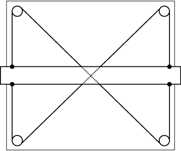 This is a standard drafting table. The horizontal bar is a straight-edge which can be moved up and down by the user. The criss-cross pattern of the cables stabilizes the bar and keeps it horizontal. |
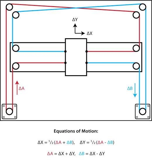
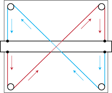 This effect can be seen by following the direction of motion of the two cables which comprise the mechanism. Note that all of the vertical arrows point in the same direction. |
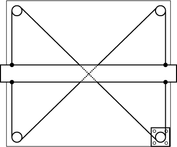 You could imagine attaching a stepper motor to one of the pulleys. Now, the horizontal bar can be moved up and down under computer control. This might be called a single-axis CNC stage. |
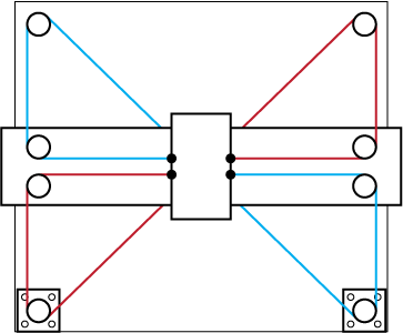 How might we modify this mechanism to convert it into a two-axis CNC stage? The illustrated mechanism above is one solution. Rotating both motors in the same direction results in horizontal motion. Rotating both motors in opposite directions results in vertical motion. |
Reference Mechanism
No Comments